ABSPrusa
Release status: Working

| Description | LM8UU Linear Bearing
Based Prusa.
|
| License | GPL
|
| Author | |
| Contributors | |
| Based-on | |
| Categories | Mendel Variations
|
| CAD Models | |
| External Link |
The ABS Prusa, is a Prusa Mendel variant which uses LM8UU linear bearings on all axes. It has a 3mm aluminium Y axis carriage, MkII PCB Heated bed with 2mm glass print surface. It uses the Melzi electronics, and requires no soldering by the builder. The printed plastic parts are printed in white ABS to a very high standard.
Contents
Bill of Materials
Printed Plastics
| Quantity | Description | Type | Comments | Diagram |
|---|---|---|---|---|
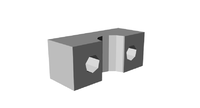
| 4 | coupling | RP | STL | 
|
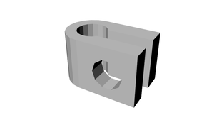
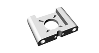
| 3 | LM8UU holder | RP | STL | 
|
| 3 | endstop-holder | RP | STL | 
|
| 1 | LM8UU x-end-idler | RP | STL | 
|
| 1 | LM8UU x-end-motor | RP | STL | 
|
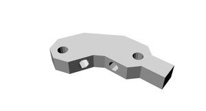
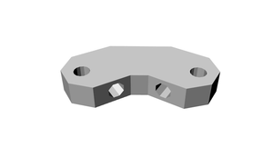
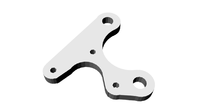
| 1 | y motor bracket | RP | STL | 
|
| 2 | z motor-mount | RP | STL | 
|
| 4 | belt clamp | RP | STL | 
|
| 8 | bar clamp | RP | STL | 
|
| 2 | rod clamp | RP | STL | 
|
| 2 | pulley | RP | STL | 
|
| 4 | frame-vertex with foot | RP | STL | 
|
| 2 | frame-vertex | RP | STL | 
|
| 1 | x carriage | RP | STL | 
|
| 1 | extruder block | RP | STL | 
|
| 1 | extruder idler block | RP | STL | 
|
| 1 | drive gear | RP | STL | 
|
| 1 | hub gear | RP | STL | 
|
Smooth Rod
- 2x 433mm 8mm stainless steel round bar
- 2x 400mm 8mm stainless steel round bar
- 2x 350mm 8mm stainless steel round bar
Threaded Rod
- 6x 370mm M8 Threaded rod
- 4X 330mm M8 Threaded rod
- 3x 470mm M8 Threaded rod
- 2x 210mm M8 Threaded rod
- 1x 50mm M8 Threaded rod
- 1x 20mm M8 Threaded rod
Nuts, Bolts & Washers
- 100x M8 Nut
- 100x M8 Lock Washer
- 10x M8 Plain Washer
- 1x M8 Nyloc Nut
- 5x M8 Mudguard Washer
- 50x M3 Nut
- 25x M3 Plain washer
- 25x M3 x10 Cap Screw
- 25x M3 x20 Cap Screw
- 5x M3 x25 Cap Screw
- 4x M3 x20 Hex Pillar
- 4x M3 x10 Grub Screw
- 10x M4 Plain Washer
- 10x M4 Nyloc Nut
- 3x M4 Bolt 20
- 2x M4 Bolt 50
- 6x M2.5 Nut
- 12x M2.5 Plain Washer
- 6x M2.5 x25 Cap Screw
- 4x 19mm Bull Dog Clips
Belts
- 840mm x 5x T5 pitch timing belt
- 900mm x 5x T5 pitch timing belt
Bearings
- 6x 608zz
- 1x 624zz bearing
- 10x LM8UU Linear
Thick Sheet
- 3mm aluminium Y axis DXF
Hot End parts
- J-Head Mk IV-B 0.4 nozzle
Electronics
- Melzi electronics (other electronics should work fine)
- PCB Heatbed MkII
Steppers
- SY42STH47-1684A 5x NEMA 17 Bipolar stepper motors
GitHub
All the ABS Prusa files are hosted on https://github.com/TheRepRapKitStore
ABS Prusa Build
Assembly
Frame assembly
In this section we will be looking at the frame assembly.
NOTE: Even if you have assembled a RepRap Prusa before please read these instructions as our frame differers slightly from the standard Prusa.
Tools
- 30cm Rule
- M8 Spanner
- M4 Spanner
- 4mm drill bit
Step 1 Frame triangles
Components
- 4x Frame Vertex with foot
- 2x Frame Vertex
- 2x Bar clamps
- 6x 370mm M8 Threaded rod
- 28x M8 Nuts Bag 1
- 28x M8 Lock Washers Bag 2
Instructions
Divide the above components in to two even sets.
Take one of the lengths of threaded rod and slide a bar clamp to the middle (see the photo to understand how the bar clamp attaches to the threaded rod). Place a washer and then a nut either side of the clamp.

Place a nut, lock washer and then a frame vertex with foot followed by a lock washer and the nut on to each end of the rod. Loosely tighten the nuts.


Attach two more lengths of threaded rod to each footed frame vertex, using a lock washer and nut either side as before.


Attach a non footed frame vertex to the connect up the triangle.
Repeat all the above instructions until you have two matching frame triangles.

Place each frame flat on you desk, using your ruler tighten the nuts until each side is 290mm (measure from plastic to plastic)

Step 2 Cross Bars
Components
- 4x Bar clamps
- 1x Y Motor bracket
- 2x 608zz Bearings
- 4x 330mm M8 Threaded rod
- 14x M8 Nuts
- 15x M8 Lock Washers
- 2x M8 Washer
- 4x M8 Mudguard Washers
Instructions
Take the Y motor mount and attach a 330mm length of rod through the bottom hole, approximately half way along the rod. Fix in place with a M8 lock washer and M8 nut either side.

Take a Bar clamp and attach in to a 330mm length of rod, approximately a quarter of the way in from one end. Fix in place with a M8 lock washer and M8 nut either side. Then attach a M8 nut and M8 lock washer half way down the rod. Attach this rod through the top hole of the Y motor mount.

Add the following components, a M8 Mudguard washer, M8 washer, 608zz bearing, M8 washer, M8 Mudguard washer and then a nut.

Add a bar clamp to the rod attaching with a M8 lock washer and M8 nut either side.

On a new 330mm length of rod attach a 608zz bearing, followed by a M8 washer, M8 Mudguard washer and M8 nut either side. Attach the remaining two bar claps either side of this, attaching with M8 lock washers and M8 nuts either side.

Step 3 Frame assembly and jigging
Components
- 26x M8 Nuts
- 24x M8 Lock Washers
- 3x 470mm Threaded Rod
Instructions
Take the rod assembly which has the two rods held apart by the Y motor mount, add a M8 nut followed by a M8 lock washer.

Take one of the frame triangles made earlier and attach the Y motor mount rod assembly through the holes in the frame vertex with foot. Attach in place with M8 lock washers and M8 nuts.

Attach the two remaining 330mm assembles to the other frame vertex with foot the same way as above. Note make sure the rods with the 608zz bearings are above the rods without bearings.

Prepare the opposite ends with M8 nut and M8 lock washer, attach the other frame triangle. Before attaching in place with a M8 lock washer and M8 nut measure the gap between the footed frame vertex's it needs to be 273mm from the inside to inside of the plastic frame vertex.


Stand the frame on the footed frame vertex's. Take a 470mm length of threaded rod slide half way through one of the holes on one of the non footed frame vertex, add a M8 lock washer, two M8 nuts and finally a washer. Slide this all the way through the opposite frame vertex hole. Turn the frame so that the side with the Y motor mount is facing you. Check that the spacing between the inside of the plastic frame vertex is 273mm as before. Maintaining this measurement adjust the rod so that there is about 85mm of rod on the right side, measure from the out side of the plastic frame vertex. Add a M8 lock washer and M8 nut to secure this rod in place at each end. Repeat this process with the second 470mm length.(NOTE the photo showes 95mm not the correct 85mm)

The four bar clamps now need to be spaced correctly, measuring from the inside of the nearest frame vertex, the nearest side of the the bar camp needs to be 70mm. The inside M8 lock washer and nut do not need to be secured yet, so just tighten them enough to secure the bar clamp.

With the Y motor mount facing you the distance from the inside of the right frame vertex to the first mud guard washer needs to be 130mm.

The two bar clamps on the bottom of the frame triangles now need spacing correctly. The distance from the frame vertex to the bar clamp needs to be 142mm. NOTE measure from the frame vertex which is on the same side as the Y motor mount.

Now take the last 470mm length of threaded rod and screw it through the bar clamps. Turn the frame so that the side with the Y motor mount is facing you. There needs to be an even amount of rod on either side of the frame.

Step 4 Z axis mounts
Components
- 2x Z motor mounts
- 2x Rod clamps
- 2x Bar clamps
- 4x M3 20mm screw
- 4x M3 nut
- 4x M3 washer
Instructions
Insert a M3 nut in to each of the nut sized holes on the inside of the two Z motor mounts.

Attach a rod clamp to each of the Z motor mounts using two M3 20mm screws each with a washer.


Attach each a Z motor mount to either side of the upper 440mm threaded rods and attach in place with a M8 washer and M8 nut.


Keeping the frame so that the Y motor mount is facing you, add a M8 nut and M8 washer to the right side of the lower 440mm threaded bar, attach to this a bar clamp, and attach in place with a M8 washer and M8 nut. Repeat on the left side.

The inside edge of the bar clamp on the right side needs to be 72mm from the out side of the nearest bar clamp.

The inside edge of the bar clamp on the left side needs to be 61mm from the out side of the nearest bar clamp.
