Opto Endstop v1.0
Contents
Opto Endstop v1.0
Overview
<div class="thumb tright"></div>Darwin's Cartesian axes all need a datum (also known as home position or end-stop) to reference their movements. At the start of each build each axis needs to back up until the datum point is reached. For Darwin, we use one opto-switch for each axis to define its position. This page tells you how to wire one up to a bracket used in Darwin's design (below).
You will need 3* (three) of these for a basic RepRap machine, and *6 (six) of them for a full machine with both home and end stops.
For those using the ZD1901 opto interrupter prevalent in the Southern Hemisphere, a simple stripboard assembly is required. Details here.
- You'll need a soldering toolkit to do most of this.
- Read our Electronics Fabrication Guide if you're new.
- Refer to the bill of materials for information on parts and where to get them.
Build It
<div class="thumb tright"></div>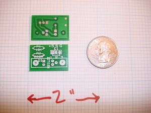
Board Bugs (listed by version)
v1.0.0
- You will need to drill the mounting holes out to 3mm diameter.
v1.0.1 and beyond
- None yet!! Please report any bugs you encounter.
Printed Circuit Board
You can either buy this PCB from the RepRap Research Foundation, or you can make your own. The image above shows the professionally manufactured Opto Endstop v1.0.0 PCB ready for soldering. Its also cheap, only $0.75 USD.
File Locations
You can download the electronics files from Sourceforge. This zip file contains the Kicad source files, PDF's, as well as the GERBER files you can use to build it yourself (or have it manufactured).
Assembly

Solder Components
<div class="thumb tright"></div>
Insert H1, R1 and R2 on the component side, and solder.
Solder Connection Wires
<div class="thumb tright"></div>
Since the Opto Endstop board essentially plugs into a stepper controller board, the easiest way is to solder the connector wires directly to the Opto Endstop PCB, and then attach a connector to the end of those wires. You will need:
- 3 wires each of different color, about 2 feet long (an old ethernet cord works well for this purpose.)
- a 3 pin, .100" pitch connector housing
- some crimp on connectors
First, strip the ends of each wire. Then you twist the ends of each wire to a point, and tin the ends with a tiny bit of solder. Insert the ends into the hole in the pcb, and solder the wire to the PCB. Take care not to have any strands of the wire cross over to the other soldering points. If this happens, use a knife or tiny screwdriver to break the connection.
Attach PCB Connector
Next, you will need to crimp on a connector to the end of the wires. This can be tricky, but it is infact do-able with the proper tools (small needle nose pliers, steady hands, patience.) After you have successfully attached connectors onto each wire, insert them into the connector housing as shown below. It is important to get the order right, as the connector must be attached to the board in the proper orientation.