ElectronicsFabricationGuide
Contents
Electronics Fabrication Guide
Many things in the RepRap project are electronics based. If you are joining the project in the early stages, or are pushing the boundaries as a developer, then there is a very large chance that you will need to make some electronics at some point in time. Here are some tips and hints to help you on your way. This is something we are very interested in automating.
Soldering
You will need a soldering toolkit to do soldering.
Soldering is the process of melting solder onto a component to make a solid, conductive, permanent bond to another part. More info on wikipedia.
Recommended Guides
We're pretty busy focusing on how to build a self-replicating 3D printer, so this guide is just a cursory look at soldering. Check out these others for a much better explanation if you're new:
Safety
- Always wear protective eyeglasses
- Work in a well ventilated area.
- Never breathe the smoke released from solder.
- Do not touch the soldering iron or fresh solder joints, they are very hot.
Preparing surfaces
The surface we're primarily concerned with is the copper side of the board that you are about to solder, but do make sure your workbench is clear of any crud that may get in your way or adhere to the bottom of the board.
Make sure there is no grease or dirt on the copper. If you're suspicious, wipe it down with a rag and alcohol, acetone or similar degreaser. Do not use paper towels - they turn to fluff rapidly.
If the copper is not bright and shiny, rub with very fine silicon carbide paper, or one of those green kitchen scouring pads. You may need to clean again. Allow the board to dry and put the lids on your solvents before commencing soldering.
Component Orientation
Certain components such as LEDs, electrolytic capacitors, diodes, and integrated circuits (chips) need to be placed in the correct orientation. Soldering them into place the wrong way can result in either your board or the component frying. In the instructions, we try and provide you hints, but sometimes we forget or gloss over something simple.
Generally, we will try to provide information on the silkscreen on the board in a few forms. First, we will try to explicitly label positive and negative pins. Also, on the PCB itself, round pads are generally negative, while square ones are positive. For components that are not positive/negative, we will provide pin #'s. There will also be an outline of the component on the board that should be helpful. For chips like the MAX232 and PIC16F628 there will be a half circle on the silkscreen that will correspond to the dimple on the chip itself.
LED Orientation
Most LED's will have two leads. One will be positive, one will be negative. Generally the longer lead is positive, while the shorter one is negative. Also, the interior of the LED can shed some light on the subject. (lol!) Here is a picture to illustrate.
Getting an LED the wrong way round won't break it, but it won't light up either.
Electrolytic Capacitor Orientation
Nearly every electrolytic capacitor will have a stripe down one side that corresponds with one of the leads. This stripe signifies which lead is the negative end. It is very important to solder these components in correctly.
If you do put one in the wrong way round, it will swell up and burst during use, likely shorting things out and generally making a mess. Avoid.
Diode Orientation
Diodes are very easy to solder in. They have two leads, and allow current to only flow one way (which is why they need to be put in the right way.) One end is usually marked with a band. On the silkscreen we will also place a corresponding band, so you will simply need to match the two up.
How to solder
Practice. The object of the exercise is to wet the surfaces of both parts you want to join with liquid metal. Once nice and shiny, they are then brought together and enough solder is added to hold them happily together. A substance called flux flows out from the solder, protecting it from the air and keeping the joint nice and shiny.
In Europe, there is a crusade against the use of lead in solder. Unfortunately the alternative "lead-free" solders are not as fluid nor as durable. If you can get leaded solder and do not plan on ingesting it, use it. All the core RepRap development team were raised on leaded solder, and look how well they turned out. OK, I see the EU's point...
When soldering stripboard, always clean it first unless it is brand, spanking new with a mirror finish (see section on stripboard).
Make sure your soldering iron tip is nice and shiny too. Wipe with moist soldering sponge (or wadded paper tissue), and if necessary scrape off accumulated crud with something stiffer like a wire brush or craft knife, using minimum force. Apply a little more solder if it is not coating, and wipe again to get that beautiful mirror finish.
If the component legs do not have a mirror finish, heat up the leg with the soldering iron and push solder onto the other side of the leg. This is good practice for understanding solder's behaviour too. Once you have pushed a coat of solder around the wire, which should take a second at most, remove solder and iron and ditch the excess solder inevitably clinging to the bit.
This process is called "tinning" and two tinned surfaces - say, a couple of wires twisted together - coat with additional solder extremely easily, forming a good electrical connection and a mechanically sound joint.
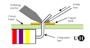
Now you can start to solder stripboard. You did remember this is a practice run, right? Put the victim part in the holes, and bend it's little legs so it stays put. Bring the soldering iron onto the copper strip near a hole with the component in it, so it touches the copper and the face of the bit is on the component leg. Push the solder in from the side, touching the point of contact between the soldering iron and the copper strip. As soon as the solder melts, divert solder only onto the now hot copper strip. If it doesn't spread around the hole itself, encourage it with the soldering iron tip.
Pull soldering iron and solder away when the solder starts to 'creep' across the copper strip. It is now flowing properly. Allow the solder to cool and set before moving the board - you'll see an obvious phase change.
Trim unwanted wires and legs off short. There are special nippers for this job, but any pliers that let you get close to the solder joint are good. Toenail cutters have been used...
When soldering, practice first on something unimportant if you're not sure. If your joints go grey and fuzzy, let the iron get hotter before using it and don't blow on the joint. Re-melt fuzzy or "dry" joints and add a tiny bit more solder so that they go shiny.
Did we mention practicing?
Also, MAKE has a great roundup of soldering tutorials.
SMD Soldering Guide
Soldering things with SMT parts can be a bit tricky. Don't worry though, we've made a straightforward guide for you to follow.
Heat-shrink Tubing
Heat-shrink tubing (or sleeving) is, as its name suggests, plastic tubing that reduces in diameter when you warm it up. We use it to insulate and reinforce soldered joints - this is important when you start dealing with several amps and an error could potentially result in a fire.
It being plastic, extreme temperatures during the shrinking process will cause it to burn and may damage nearby wires. Hot air guns like supercharged hairdryers are used industrially. Untidy results can be achieved with a soldering iron barrel or a lighter flame. The best domestic heat source is the hot air coming off the element of a small, gas-powered soldering iron - some gas soldering irons have special attachments but these are only generally useful if you're not soldering at the same time.
Choose a diameter of heatshrink that fits easily over the wire and joint that you wish to insulate. Ensure the joint is smooth with no sharp edges, or the heatshrink will be perforated. If you have to slide the heatshrink on before making the joint, do not allow it to get too close or it will shrink prematurely and cause swearing. If the joint and the wire are different sizes, use two sizes of heatshrink and overlap them.
Heatshrink is also available with hot-melt adhesive on the inside. If you use it, fine, but it is not necessary to go to the expense of hunting it down for the RepRap project's components. It is also a real beggar to remove.
Making Circuit Boards
Printed Circuit Boards (PCBs)
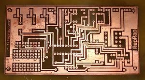
Making a PCB is an essential part of making your own RepRap machine. You start with a blank copper clad board and then proceed to transfer the circuit design to the board, and then remove the non-circuit copper from the board by etching.
We have compiled a nice guide for you, but you may also find lots of good guides elsewhere on the internet.
Stripboard Circuits
Stripboard is commonly used for making small runs of simple circuits. It has a matrix of small holes on a 2.5mm grid, connected in stripes on the reverse by lines of copper. It is readily available from electronic hobbyist suppliers worldwide. Maufacturers include Datak and Vero.
The strips on the back of the board need to be "separated" at certain points, to remove undesired connections between components placed on the board. The easiest way to do this is to use a small electric drill with a drill bit around 3-4mm in diameter. Don't drill all the way, just far enough to cut the copper tracks - you may find a 3.5mm drill in a hand-held chuck is easier to control.
Use a small scaper to scrape off any copper track resiude from the strip separation process.
The strips then need to be cleaned to ensure oxide and grime accumulated in storage are removed. Methylated spirit and MEK are a good de-greasers. If oxide is a problem, and the copper is not perfectly shiny, run a fine silicon carbide paper over it. No fine paper? Use one of those green scrubbing pads from the kitchen. If spouse disapproves, use "Brasso", wipe down well and replace ruined cleaning pad...
If you should cut a strip in the wrong place, solder a wire jumper over the top. It is a good idea to isolate mounting holes too.
Pre-soldering testing
Before ever connecting power to a newly made stripboard it is essential to test the board. One common problem is flakes of copper spanning tracks and causing shorts. Test the following:
- Use a multimeter to check for any conductance between tracks. Check every track against its neighbour. There should be no conductivity.
- Make sure you check around every separation point to ensure there is no conductivity.
Post-soldering testing
- Use a multimeter again to check for any conductivity between unrelated tracks.
- Check that there is conductivity between tracks that are connected by jumpers or resistors.


