McWire Cartesian Bot 1 2 (Death March: Do not build!!!)
Contents
This page is under construction. It should be done by February 2008. Stay tuned!
McWire Cartesian Bot v1.2
Introduction
This design is based on a previous design by Tom McGuire, and was named after him. We have since taken his design and improved upon it in a few crucial areas and adapted it for our particular needs. We are very grateful and appreciate the hard work he put in. All of our subsequent work is released under the GPL.
Purpose
The McWire Cartesian Bot is a 3 axis cartesian robot designed for light milling, additive 3D printing, laser cutting / etching, and pen plotting. The design strategy has focused on ease of construction, maintenance, and operation. We also tried our hardest to minimize cost while providing a robust 3D positioning system. The result is a machine that provides smooth, high quality motion while keeping costs under $250. We hope you enjoy this project as much as we have.
Operational Theory
The basic operation of the cartesian bot is that there are 3 'stages', or 'axes' that each move in a different direction. Looking from the front of the machine, the X Stage moves left to right, the Y Stage moves front to back, and the Z Stage moves up and down. Each stage is driven by a 'leadscrew'. What this means is that a nut is attached to each stage so that it cannot rotate. A length of threaded rod is run through the nut and attached to a motor. When the motor turns the threaded rod it forces the nut (as well as the stage) to move in one direction. The combination of all 3 axes allows us to position a tool head at any arbitrary point in 3 dimensional space.
Prepare Raw Materials
There are a variety of raw materials you will need to construct your bot. Its a good idea to get all of them on hand before you assemble your machine just to make sure you have everything. Trust me, theres nothing more frustrating than assembling all the components and realizing you are missing one minor part that makes it all work.
Tools Required
At the minimum, you will need the following:
- Drill press, although you could get by with a power drill.
- Power Drill
- Screwdriver
- Hacksaw
- Pliers
- Pipe wrench
- Scissors
- Printer
- A vise
- Sandpaper: rough, medium, and fine
If you are making your own acrylic sheets, you will need:
- A jigsaw, or other tool to cut curves.
- A special countersinking bit
Bill of Materials
You should refer to our online parts lister that has details on the parts needed, as well as where to get them. We also have the parts listed on a Google spreadsheet that is embedded below.
<iframe width='550' height='800' frameborder='0' src='http://spreadsheets.google.com/pub?key=pmEMxYRcQzzATwbOb71BmGA&output=html&gid=22&single=true&widget=true'></iframe>
Structural Components
The main structure of the bot is made from 3/4" steel pipe. This is the same kind of pipe used for plumbing. It is relatively cheap, easy to find, and easy to assemble. Pictured below are all the parts required to assemble it.
Aluminum Rails
The aluminum rails provide 2 important functions: they ensure that the stage moves in a straight direction and only that direction, as well as providing a bearing surface to handle the load of the stage. You will need 2 rails per axis, and a grand total of 6 rails. The rails are pictured below.
Aluminum Supports
For added rigidity of the aluminum rails, as well as a convenient place to mount the stepper motors and endstop switches, we use lengths of 90 degree aluminum angle. Each piece of aluminum is bolted to the ends of the aluminum rails. The stepper motors are then bolted to these supports, as are the optical endstops. A convenient side effect of this is that the entire aluminum rail assembly acts as a heat sink for the stepper motors, allowing them to run at very low temperatures. The supports are pictured below.
Acrylic Cutouts
The most complicated part of the system are the acrylic pieces. For your convenience, the RRRF will be doing a bulk order of lasercut pieces. If you prefer to create your own pieces, the digital files used to create them are available. You could either have them lasercut yourself, or you are skilled enough, you could print them onto a full page sticker, place the sticker on acrylic, wood, or some other flat piece and then cut/drill in the appropriate places. The design has intentionally kept each piece small enough that it could fit onto a 8.5" x 11" sheet of paper.
Teflon Bearings
<div class="thumb tright"></div>The teflon bearings are one of the major improvements made to the original design by Tom McGuire. Teflon has the lowest coefficient of friction of any plastic, and is ideally suited as a bearing material. It turns out that McMaster supplies teflon in 1/2" long strips which are easily made into bearings. Simply cut them to length, drill a hole on each side and then attach them to the stage with screws. We've even provided a sticker template that will help you drill the holes in the proper place.
Springs
You'll need various springs to keep the different parts of the machine in contact and such. In some parts they keep the bearing arms pulled together which keeps the stages pressed up against the aluminum rails. On the Z axis, they also keep the Z Stage pressed up against the rails, as well as provide a counteraction to gravity to reduce missed steps and lessen the force on the Z stage motor and coupling.
Leadscrews
The leadscrews are the part of the system that drives each stage. Some systems use leadscrews that cost as much as our entire machine, but instead we use simple 1/4"-20 threaded rod that you can find at a hardware store. We order it from McMaster which means its usually very straight. If you buy it from a local hardware store, make sure you spend some time looking along the length of the rod to make sure it is straight. This is one of the single most important parts to make your machine run smoothly.
Roller Bearings
<div class="thumb tright"></div>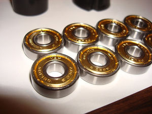
The roller bearings fulfill a variety of functions, but primarily they allow the machine to run smoothly. Along with the springs, they also ensure that the stages are all tight up against the rails they run on. We've decided to use standard skate wheel bearings. They are cheap, ubiquitous, high quality and awesome. Whats more steampunk than going into a local skate shop and pick up a set of skate bearings to build your self-replicating robot? A bunch are pictured below.
Various Fasteners
You will need various nuts, bolts, washers, and screws to assemble your machine. We have listed them all in the bill of materials and the picture to the right should theoretically be all the parts you need. It wouldn't hurt to have extras on hand since its easy to drop a nut and lose it.
Preparatory Work
Cut Aluminum Rails To Length
You will need to cut your rails to the specified lengths. I recommend using a hacksaw and some clamps. Cut slowly and you can be very precise. Cut from the bottom of the U to the top. Remember: measure twice, cut once!
X Rails (2) - ?? inches Y Rails (2) - ?? inches Z Rails (2) - ?? inches
Cut Aluminum Angle to Length
X Supports (2) - ?? inches Y Supports (2) - ?? inches Z Supports (2) - ?? inches
Cut Threaded Rod to Length
The best way to cut small threaded rod like this is with a Dremel and a cutoff wheel. If that is not available, a hacksaw and a clamp will work. Take care not to bend the rods or damage the threads. Also, its a good idea to put a nut on the rod before you cut it, so that you can 'fix' the threads at the cut end by unscrewing the nut. Do not cut through the nut itself!!!
X Leadscrew (1) - ?? inches Y Leadscrew (1) - ?? inches Z Leadscrew (1) - ?? inches
Countersink the Acrylic Cutouts
In order to get the proper clearances from the mounting hardware, various mounting holes need to be countersunk. This means you use an angled drill bit that drills the acrylic so that the top of the screws sit flush with the surface of the acrylic. If you get the lasercut boards from the RRRF, this will already be done for you. If you build your own, you will need to do it yourself. The pictures below show each piece to be countersunk, as well as which side to do the countersinking on. Be careful to do it on the side that needs it, as it is important which side you do it to.
Assemble Machine
Structure
Once you have everything ready, you will want to start by assembling the pipes. I like to start with the base and work my way up to the vertical components. Here is the order I generally use:
- Put the pipe caps on the 12" pipes.
- Put the 90 degree elbows on the 12" pipes.
- Put a 9" pipe on one of the elbows.
- Put the 3 way tee on the 9" pipe.
- Put another 9" pipe on the other end of the tee.
- Flip it up and screw on the other 12" pipe assembly.
- Put the remaining 9" pipe in the vertical part of the tee.
- Put the elbow on the top of the 9" pipe.
- Put the 6" pipe in the other end of the elbow.
- Put the flange on the end of the 6" pipe.
Once you have them all assembled, you will need to tighten them and get them all in the proper positions. you can push on opposite corners of the 'square' formed by the bottom parts to get it to lay flat, and can use your pipe wrench to get the other pieces tight. Once you have a feel for how everything works, you may want to undo everything and then re-assemble it using thread locker to make the pipes stay in position better. You may want to delay this until the very end so that you make sure the whole thing works properly.
Also, don't put thread locker onto the flange just yet, you need to attach the Vertical Base and align it before you make it permanent. Do not put thread locker onto the 'legs' of the base either, you'll need to remove those in order to drill them.
X Stage
Now that you have the structure assembled, you will want to start by assembling the X Stage. We have provided a PDF printout that you can print onto a sticker, cut out, and apply to the pipes that will provide you with guides of where to drill into the pipe to mount the X stage rails. Its highly recommended that you use these stickers. It will make your life easier, and make your machine work better.
Cut out the stickers, and be careful to not cut on the lines. Once you have them cut out, cut along the line on one end of each of the stickers you just cut. Be very precise when you do this. You will then take this edge and line it up with the pipe where the threads end. Apply the sticker along the length of the pipe on the top. When you have applied both stickers, you will want to prepare the holes for drilling. Take a center punch (or sharp screw/nail) and use it to make a small indentation in the center of the holes where it shows you to.
After you have made the indentations, ideally remove the pipes and take them to your drill press. If you do not have a drill press, keep them attached and get your power drill. You will want to drill through the pipes with a x/x" drill bit. It is a good idea to use cutting oil (3-in-1 oil works just fine) Place a bit of oil on the spot to be drilled and begin drilling. Do not force the drill to much and take your time. The pipes are actually relatively easy to drill through if you have a decent drill bit.
Now it is time to assemble the frame stage. Basically, you want to lay out both rails next to each other, then eyeball where to drill a hole so that the rails will be mounted with their ends sticking out the same amount. Alternatively, you could measure about 2.5" from the ends of both rails and make a mark where the hole should be. Either way is fine and I've had good results by simply eyeballing it.
Once you have drilled the aluminum rails, its time to attach them to the steel pipes. Get some of the 3/4" thread cutting screws out, as well as your power drill. You can do it with a normal screwdriver, but it does take a decent amount of force to cut threads into the steel pipes. Give it some juice, and soon you will have firmly attached aluminum rails.
Now that your aluminum rails are done, its time to attach the supports. Take the X support stickers, and apply them to the top side of the supports. Take care to carefully apply them so that they are well aligned with the edges. it is mostly important to align the front of the sticker template with the front of the support. Once you have the stickers attached, carefully drill out the mounting holes. Drill the two large holes out at 5/16", and drill the two small optical endstop mounting holes out at 1/8".
Once you have the mounting holes drilled,
TODO:
- Supports
- Motor Mounts
- Acrylic Stage
- PTFE Bearings
- Roller Bearings
- Drive Nut
- Lead Screw
- Limit Switches
- Test + Tighten
Y Stage
Very similar to X Stage
Z Stage
Similar to X + Y Stages
- Vertical Bearing Arms*
Electronics
The electronics are the brains of the system. We have developed 2 electronics systems: a first generation based on the PIC and a second 'experimental' system based on Arduino. The second generation is still experimental, but is much easier to work with.
Continue reading about the electronics systems or skip to the Arduino based electronics.