Generation 2 Electronics
Contents
- 1 Arduino and Sanguino Based Electronics
- 1.1 Overview
- 1.2 Power Supply
- 1.3 Individual Boards
- 1.4 Wire It Up
- 1.5 Mounting and Wiring
- 1.6 Program the Firmware.
Arduino and Sanguino Based Electronics
Overview
Once you start putting electricity into your RepRap - even at just 12 volts - you have to take basic, common sense precautions to avoid fires. Just in case these fail, test your workshop smoke detector. Got no smoke detector? Get one!
Power Supply

The RepRap machine needs a regulated power supply giving at least 8 amps at 12 volts. The easiest way to do this is to convert a normal PC power supply into a RepRap power supply. Its simple, cheap, and all the boards are designed to accept the standard Molex connectors that are common on ATX power supplies.
More info and setup instructions here.
Individual Boards
Parts List
<iframe width='500' height='300' frameborder='0' src='http://spreadsheets.google.com/pub?key=pmEMxYRcQzzATwbOb71BmGA&output=html&gid=30&single=true&widget=true'></iframe>
Arduino, Arduino Clones, and Sanguino

Arduino is an open source project that has created an easy and powerful microcontroller board based on the Atmel ATmega168. It is the brain of the RepRap electronics. You can get a premade Arduino, you can buy and assemble a kit, or you can even make it from scratch yourself. They all look the same to the rest of the electronics or to your computer. You will need an Arduino Nano, Diecimila, or Duemilanove or the latest equivalent.

Alternatively, you can use the Sanguino. Sanguino is an Arduino-compatible board based on the ATmega644P that was developed as a spinoff of the RepRap project by Zach Smith. It has four times the flash memory, four times the RAM, and many more pins than the Arduino. You can drive a RepRap with a standard Sanguino, but there will also soon be a special Sanguino RepRap Motherboard that makes the connections easier, has an SD card slot, and all sorts of other goodies.
There is yet another possibility: a Mega 2560 that is packaged on the standard Arduino footprint: MegaNano2560 This has the large memory capacity of a Mega2560 in the original footprint.
A standard Darwin RepRap will run happily off an Arduino, but if you want expandability and upwards-compatibility for the future, go for the Sanguino.
Stepper Motor Driver v2.3
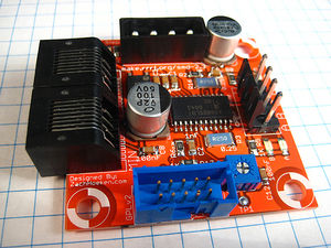
Each stepper driver board drives one of the stepper motors. You need three of these boards for a fully functioning RepRap. Each board controls the position of one axis. Together, they position the print head anywhere in the 3 dimensional build area.
More info and build instructions here.
Any earlier version of Stepper Motor Drivers back to v1.0 should work as well. For a few notes of comparison, see [1].
DC Motor Driver v1.1
This board is capable of controlling two low current DC Motors in both forward and reverse. It has a speed/direction interface and is easy to control.
More info and build instructions here.
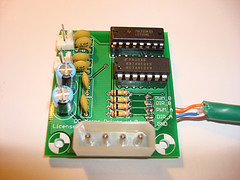
PWM Driver v1.1

This board is capable of driving medium DC loads with TIP120 power transistors. It has a PWM interface and is also easy to control.
More info and build instructions here.
Opto Endstop v2.1
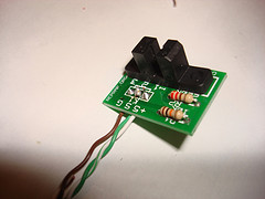
All of a RepRap's axes all need a datum (also known as home position or end-stop) to reference their movements. At the start of each build each axis needs to back up until the datum point is reached. We use one opto-switch for each axis to define its position. This page tells you how to wire one up.
More info and build instructions here.
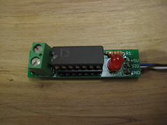
Temperature Sensor v1.1
This sensor allows you to read a thermistor as an analog value. It is a very small and simple helper board.
More info and build instructions here.
Optional Boards
These boards are not required, but can be used to improve your machine or do different things.
Thermocouple Sensor v1.0
The thermocouple sensor is a different type of temperature sensor board. Unlike the thermistor based temperature sensor which can only really handle temperatures up to 300C, the thermocouple sensor can handle temperatures up to and over 1000C. It uses a thermocouple for temperature measurement, and it is much easier to read values from (as well as being a bit more accurate over a wider range.
Pro's: This board may be especially interesting if you're tight on memory space on the Arduino, using the thermocouple will allow you to leave out thermistor conversion tables. It also saves you the hassle of calibrating a thermistor. It will probably give a more accurate result (within 1-2 'C).
Con's: Unfortunately, it is also more expensive (by about $25)
More info and build instructions here.
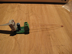
Magnetic Rotary Encoder v1.0
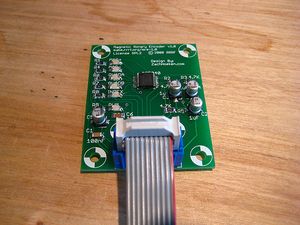
The magnetic rotary encoder is an optional board to determine the rotational speed of the extruder motor. A different method is laser-cut version, using a H21L0I (also used for endstops).
Pro's: Allows you to achieve better print quality than with open-loop controlling (without feedback) of the extruder motor.
Con's: Slightly added complexity due to another board in the system. The costs. Also, this board is surface mounted technology (SMT), which is slightly harder to solder and needs some extra (inexpensive) tools, such as a flux pen.
More info and build instructions here.
Arduino breakout shield
This is a board that allows you to make screw-tab connections to the Arduino: less fiddly than the standard connections. See details here.
Wire It Up
Now that all the boards are created, you'll need to wire it all up. One of the main advantages of the Arduino/Sanguino based system is that it is highly configurable. Each board can be wired to the microcontroller in a number of ways. The Arduino can use the SNAP communications protocol or G Codes. SNAP is compatible with the older PIC RepRap control system. G Codes are the newer and more versatile way of controlling the machine. The Sanguino just uses G Codes.
Wiring up with an Arduino

This is how to run an entire RepRap machine off of a single Arduino. The Arduino can simply be powered directly off the USB port of your computer. The only real downside is that the code takes up most of the space on the Arduino, and every single pin is in use. Basically, there is not much room for hacking either the firmware or the electronics... but it will definitely get you printing in a minimum of time and effort.
The Max endstops are optional; they are seldom used in practice. Indeed, if you're using an extruder with a valve, that takes up the pin used by Z Max.
Click for a bigger circuit diagram. This wiring diagram is available as an Eagle file in the RepRap repository here.
An example how it works for User:Fenn:
D0 RX
D1 TX
D2 X step
D3 X dir
D4 X min
D5 fan
D6 heater
D7 Y dir
D8 Y min
D9 X max
D10 Y step
D11 extruder motor pwm
D12 extruder motor dir
D13 Y max
A0 (D14) thermistor
A1 (D15) valve pwm
A2 (D16) valve dir/Z max
A3 (D17) Z min
A4 (D18) Z dir
A5 (D19) Z step
Wiring up with a Sanguino

The Sanguino can simply be powered directly off the USB port of your computer, but it needs a USB->serial connector wire such as this one. There is plenty of room for code and data in the Sanguino, and no shortage of input and output pins.
As with the Arduino, the Max endstops are still optional; however, there is no shortage of Sanguino pins, so (apart from economics...) there is no reason to do without them.
Click for a bigger circuit diagram. This wiring diagram is available as an Eagle file in the RepRap repository here.
The diagram shows Extruder 0 wired for the new stepper-motor pinch-wheel extruder and Extruder 1 wired for the older DC-motor driven extruder.
Mounting and Wiring
There are two alternatives here. You can put all the electronics in one place, and run wires from it to the components of your RepRap machine, or you can clamp the various circuit boards to the machine next to the devices they control and run control signal wires to them from the Sanguino/Arduino.
Electronics all in one place
First, find or cut a flat piece of thin plywood, about 300mm x 300 mm (12" x 12").
Next, place all your boards on the wood so that each board is close to where it will be wired to. Mark with a pencil through each hole, and also optionally around each board for drill holes and as a board outline.
Then, take all the boards off and drill a blind hole at each drill mark with a 2mm drill bit. (Use 3mm if you want to use nuts and bolts and drill right through - see below.)
Take a foot or so of silicone aquarium tubing and cut 5 mm (1/4") lengths of it. You will be using these to mount the boards to the wood. Optionally, you can use spacers if you want a more professional look.
Mount each PCB on the board using small round-headed woodscrews. Use the lengths of silicone tube as spacers between the wood and the PCBs.
Alternatively, mount each board on to the wood with M3 x 15mm bolts. Use washers on both sides, and use a short piece of tubing between the board and the wood for spacing (and shock absorbtion). Tighten down the nut by hand, and then a little bit with pliers or a wrench. It should be solidly attached, but not wrenched down too much. (For the brits: dont use too much welly ;)
Electronics distributed around the machine.

There are U-shaped PCB clamps in the RP parts for RepRap. These allow PCBs to be clamped to the 8mm rods that form the frame.
X, Y, and Z are the stepper controls for those axes. M is the microcontroller (this is the Sanguino, but the Arduino goes in the same place). The extruder control boards are at E behind the X stepper on the carriage.
Lasercut kits may use cable-ties, or excess small clamps normally used for clamping drive chain or drive belts.
Wiring connections
Once you have the boards laid out and mounted, its time to wire them up. Currently, there are four different ways to hook the boards up to your Arduino/Sanguino:
- Strip 5 mm (1/4") from the end of the wire, and stick it directly into the header on the Arduino/Sanguino. This is the easiest, but also most prone to failure (the wires will vibrate out, break, etc.) This works much better with single-strand wire than multi-strand.
- Solder each wire to a .100 pin strip, and plug that directly into the appropriate spot on the Sanguino/Arduino. This is the hardest method, but it is the most permanent. The downside is that its hard to reconfigure your system without resoldering everything.
- Solder each wire to an individuaL .100 pin strip pin, put a little heat-shrink on the join, and plug that directly into the appropriate spot on the Sanguino/Arduino. This is more fiddly, but more reconfigurable and versatile. It gives reliable connections too.
- There is an Arduino and a Sanguino breakout shield which you can insert into the Arduino or Sanguino to provide the same access to the pins, but in a screw terminal form-factor. This gives a nice blend of easy configuration, with a strong, semi-permanent connection.
Program the Firmware.
The firmware is what controls the electronics and tells them what to do. Read more about how to do this on the 2nd generation firmware page.