Temperature Sensor v1.0
Note: This is an experimental 'next-generation' prototype.
Temperature Sensor v1.0
Overview
<div class="thumb tright"></div>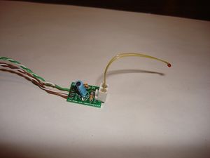
- You'll need a soldering toolkit to do most of this.
- Read our Electronics Fabrication Guide if you're new.
Get It!
Raw Components
Files
You can download the electronics files from Sourceforge.
This file contains the following:
- GERBER files for getting it manufactured
- PDF files of the schematic, copper layers, and silkscreen
- Eagle source files for modification
- 3D rendered image as well as POVRay scene file
- exerciser code to test your board.
Interface
| Pin | Function |
| +5 | This is the pin to supply +5 volts on. |
| S | This is the signal pin. It will output a voltage between 0 and 5 volts that correlates with the temperature. |
| G | This is the ground pin. |
Signal Values
The thermistor circuit is a voltage divider that can be read with an ADC such as the one on an Arduino board. That value can then be run through a formula to get the temperature in degrees. This circuit has been documented in full detail in a blog entry by nophead.
Thermistor Values
Each thermistor has its own beta value. A table of values for our thermistors will be shown below.
| Thermistor | Beta | More info | Pic |
| RRRF 10K Thermistor | Mouser | pic | |
| RS 10K Thermistor | 3480 | 484-0149 | pic |
Build It
Board Bugs (listed by version)
v1.0
- No bugs yet, please report any you find to the forums.
Printed Circuit Board
<div class="thumb tright"></div>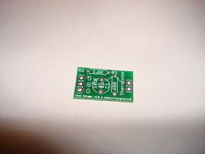
You can either buy this PCB from the RepRap Research Foundation, or you can make your own. The image above shows the professionally manufactured PCB ready for soldering. Its also cheap, only $0.50 USD.
Components
<div class="thumb tright"></div>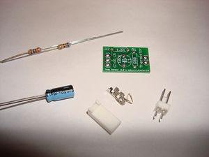
<iframe width='500' height='330' frameborder='0' src='http://spreadsheets.google.com/pub?key=pmEMxYRcQzzATwbOb71BmGA&output=html&gid=26&single=true&widget=true'></iframe>
Soldering Instructions
<div class="thumb tright"></div>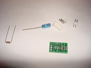
R1
You can insert the resistor in any orientation. Pay attention to the color bands.
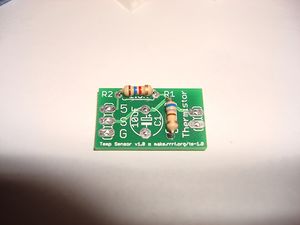
R2
You can insert the resistor in any orientation. Pay attention to the color bands.
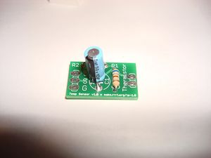
C1
Electrolytic capacitors have a polarity. Make sure the stripe on yours matches the one in the picture.
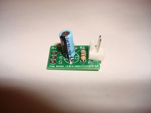
X1
Make sure you insert the connector correctly: with the tab facing the inside of the board.
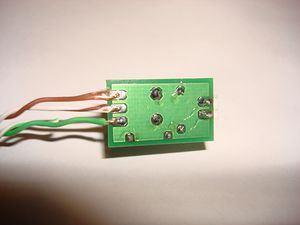
Wires
Trim 1/4" from the end of each wire. Insert that wire into the hole in the pad and solder the correct wire to the correct pad using the table below:
| Pad | Color |
| +5 | Green |
| S | White/Brown |
| G | Brown
|