Use Sanguish
Release status: working

| Description | All in one electronics with Toshiba drivers
|
| License | [GPL]
|
| Author | |
| Contributors | |
| Based-on | |
| Categories | |
| CAD Models | |
| External Link | (none)
|
Sanguish Home ----- Build Sanguish1.0 ----- Firmware for Sanguish
Contents
Warnings !!!
Never insert or remove drivers while the board is powered.
Don't plug or unplug stepper motors while the driver 12V is on. You can plug or unplug steppers if the board is powered as long as the 12V driver relay is off. (As shown by the indicator LED near the relay.)
Be careful when wiring the stepper motor plugs and when plugging them in to avoid shorting one coil to another. The stepper connectors are pretty standard, with one coil on each side of the connector. Be sure that neither of the coils are allowed to span across the middle of the connector. Doing so will likely burn out the driver.
Be careful not to plug the stepper connector in shifted to the side. This will short across the coil outputs and likely burn out the driver. Double check that the connector is centered on the pin header before powering on.
MCP2200 USB to Serial
Instructions coming soon. For now see Gen7 wiki or the Microchip MCP2200 product pageMCP2200 product page.
Arduino Setup
The ATmega in the kit comes with the Gen7 bootloader installed. See Gen7_Arduino_IDE_Support for instructions on adding the board support. Then make sure to select the Gen7 ATMega 1284P 20Mhz board. You'll need a jumper on the RST pins while loading new firmware. You may take it off for normal operation.
Host Software Setup
The ATMega comes with Repetier firmware installed. Repetier like some other firmwares uses EEprom storage to store calibration settings. This means you can adjust common calibration settings without flashing the whole firmware again. If you wish to get started without loading a custom firmware, you could simply skip the Arduino stuff and just install Repetier host software. Set it to the com port that your board uses and 115200 baud. Once you get a connection you can adjust most of the calibration settings in the EEprom directly from Repetier host without going back to Arduino.
Connections
Be careful when connecting up the electronics. Impropper connections can fry the board.
Power
There are two screw terminal power input connectors on the board.
The first is for motor power and supplies the 7805 voltage regulator which provides 5V to the logic level components. Be careful not to connect the voltage in reverse. Reverse polarity voltage may burn out sensitive components. Be sure you built the board per directions for 12V vs. 24V supply. For 24V supply you will need to add a current limiting resistor for the relay coil and will need to heatsink the 7805 Regulator.
The second is for heater power. If you are going to use 24V supply for this make sure you are using heaters designed for 24V. Using Prusa HBP at 24V for instance will result in severely overpowering the bed and may cause a fire. Similarly at hot end designed for 12V has too low a resistance to cope with a 24V supply generally speaking.
Motors
Motors are connected with one coil on the first two pins and the other coil on the 3rd and 4th pins of the stepper driver connector. Pin designations are BM BP AM AP. If a single coil is accidentally connected across the connector A to B the driver may burn out. For instance an incorrectly wired stepper connector might connect the A coil to BP and AM, or BM and AP. This may also happen if you wire the connector correctly but insert it incorrectly with the connector shifted over one pin. It is a good idea to check your stepper connectors before plugging them in. The first two wires (BM and BP) should have a low resistance between them as should the second pair (AM and AP). There should be no connection between any A and B pins.
Thermistors
Thermistors can be connected in either direction. They are not polar components. Be careful when wiring and securing the thermistor to prevent shorts. Depending on the firmware a short will show up as very high or very low temperature readings.
End Stops
End stops are wired like Gen7. Pins are labeled on the board. S is the signal pin, g is ground and 5V is the 5V supply. The main thing here is to make sure that the endstop does not short 5V to ground when activated.
USB to Serial
There are two USB to serial cable headers. If you are planning to use the built in MCP2200 then you can leave them unpopulated. The header at the edge of the board matches the FTDI cable used for Gen3, Gen7 etc. The other header matches some other USB-Serial pinouts as well as some bluetooth adapter pinouts. Bluetooth testing is comming soon.
Jumper Settings
Older Beta files
File:Sanguish Beta Cheat Sheet.pdf
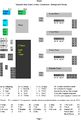
Cheat sheet for Sanguish Beta board
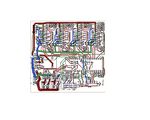
Sanguish Beta Layout
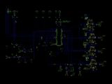
Sanguish Beta Schematic

