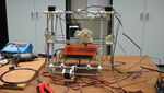
Clone wars: Ronquío
|
English • العربية • български • català • čeština • Deutsch • Ελληνικά • español • فارسی • français • hrvatski • magyar • italiano • română • 日本語 • 한국어 • lietuvių • Nederlands • norsk • polski • português • русский • Türkçe • українська • 中文(中国大陆) • 中文(台灣) • עברית • azərbaycanca • |
is under construction
Intro
- This printer is being constructed at and to University of Jaén and this is in the clone wars project.All printable parts have been obtained as donación by multiXtruder project, with the participation of Alberto Valero Gómez and Juan Pablo Rodríguez.
- To assemble this Reprap has followed the guide assembly Prusa 2 Juan González Gómez(Obijuan)
- This page will attempt to document all the peculiarities of this Reprap and amendments to be made
- Clone number XX
Mentions
Author
- José Antonio Pérez Caparrós
Record
 |
|
 |
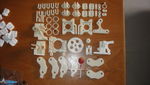
Printed Parts
Full structure
| Picture | Piece (STL) | Quantity | Comments |
|---|---|---|---|

|
Bar Clamp | 8 | Original Bar Clamp |

|
frame vertex with foot | 4 | original frame vertex with foot |

|
Frame vertex | 2 | Original Frame vertex |

|
Y motor bracket | 1 | Original Y motor bracket |

|
z motor mount | 1 | Z motor mount |

|
z motor mount | 1 | Z motor mount |

|
belt clamp | 2 | Belt clamp |

|
Belt clamp nut holder | 2 | Belt clamp nut holder |

|
Bearing guide | 3 | Bearing guide |

|
LM8UU Holder | 3 | LM8UU Holder |

|
jonaskuehling_x-ends_threadedrod_idler | 1 | Ends threadedrod idler |

|
ends_threadedrod_motor | 1 | Ends threadedrod motor |

|
x-carriage | 1 | X carrige |

|
coupling | 2 | Coupling |

|
endstop-holder | 3 | Endstop-holder |
Extruder: Jonaskuehling
| Picture | Piece (STL) | Quantity | Comments |
|---|---|---|---|

|
jonaskuehling_gregs-wade-v3_jhead | 1 | Greg's Wade reloaded |

|
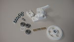
biggearmod_fixed | 1 | Big gear |

|
smallgearmod_fixed | 1 | Small gear |
Vitamins
In the area of self-replicating printers (repraps) are called vitamins to the parts that non-printable and you have buy them.
| Picture | Piece | Quantity | Comments |
|---|---|---|---|

|
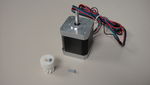
Stepper motors Nema 17 | 5 | 1 for x axis, 1 for y axis, 2 for z axis, 1 for extruder. |

|
Belts open T2.5, 50mm wide. Lengths: 840mm(axis Y), 920mm (axis x) | 2 | T5 belts are also valid. They are those used in the Prusa 1, but with the T2.5 is a more accurate. |

|
Metal pulleys T2.5 or SLS | 2 | You can also print, but it has to be with a nozzle 0.35mm. |

|
Linear bearing LM8UU | 10 | It takes 3 to axis x, 3 to y axis, 4 to z axis Prusa 2 in original. Optionally one can add more to the axis y. There are also trucks that come with x-axis 4. But not necessary. |

|
608 zz bearings | 6 | They are the same as those used in inline skates. Needed: 2 for the Y axis, 1 for x, 3 for the extruder |

|
M8 threaded rod 1m long | 6 | The rods must be cut later |

|
M8 smooth rods of stainless steel (1m long) | 3 | If purchased by meters, you have to cut later. There are suppliers who sell already cut |

|
M8 nuts | 100 | It takes less nuts, but better to have too not missing. A ~ 78 are used a function of structure as mountains, the extruder and the pulley X. |

|
Normal M8 washers | 100 | Less washers are needed, but better to have too not missing. They use about one per nut but can do more to align missing bolt extruder or to alienate any item. There are nuts which can be dispensed washer. |

|
Clamps 2.5mm wide and 120mm long | 14 | 3 To the carriage linear bearings axis x, 4 to the z-axis linear bearings, 6 to axis y linear bearings. 1 To base´s terminals of axis y. |

|
Screws M3 x 10mm | 20 | 8 to 2 motors axis z, 3 to motor axis y, 3 to motor extruder, 6 to screw the supports of the bearing axis and wood base. |

|
Screws M3 x 12mm | 3 | 3 to motor axis x. Also you could use 3 M3x10mm |

|
Screws M3 x 16mm | 8 | 4 to belt clamps of x axis. Others 4 to y axis. |

|
Screws M3 x 20mm | 4 | 2 for each bar clamp brackets screwed to z-axis motors. |

|
Screws M3 x 25mm | 8 | 4 for each of two shaft couplings z. |

|
M3 nuts | 23 | Most parts are embedded in printable pieces. |

|
M3 Washers, normal width | 35 | For most M3 screws
|

|
Screw M3 x 40mm | -- | -- |

|
Allen head bolt M3 | 3 | If you can not find it, put a screw M3x10 in place. |

|
Screw M4 x 20mm | -- | -- |

|
Washer M4 | -- | -- |

|
M4 Hex nut | -- | -- |

|
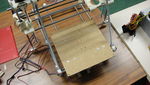
Wood Base 22x22 cm and thickness 3-4mm | 1 | For the y axis Base, where brackets bearing are bolted. Need not be made of wood, may be methacrylate, aluminum or other material. |

|
terminals | 4 | Block of 4 terminals to wooden base y axis. |

|
Stationery Clips | 4 | Hold the glass or mirror to hot bed. |

|
Glass or mirror 20x20cm | 1 | Used as printer dock (because they are very flat) |

|
Kaptom tape | 1 | Used to put it on glass or mirror and the plastic stick better. Also used to fix thermistor hot bed. |

|
vinyl tubing, 5 mm inner diameter and 2cm long. | 2 | It is placed on the motor shafts z to grip the coupling z. |
Vitamins for extruder
| Picture | Piece | Quantity | Comments |
|---|---|---|---|

|
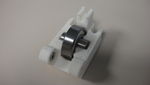
M8 bolt | 1 | 1 to extruder |
Threaded rods
In total needed 6 M8 threaded rods 1m long. It should be cut to the following sizes:

Smooth rods

|
We are needed 6 rods, of the following sizes:
|
Electro mechanical
| Picture | Piece | Quantity | Picture | Piece | Quantity |
|---|---|---|---|---|---|

|
Allegro 4982 | 4 | 
|
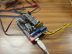
Arduino Mega 2560 | 1 |

|
RAMPS 1.4 | 1 | 
|
Hot End JHead Mk VB | 1 |
|
|
Stepper motors Nema 17 | 5 | 
|
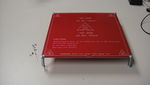
Hot bed MK2 | 1 |

|
End stop | 3 | |
Thermistor hot bed 100K | 1 |

|
LCD 20x4 | 1 | 
|
Keypad | 1 |
RAMPS 1.4
http://www.reprap.org/wiki/RAMPS_1.4 http://www.reprap.org/wiki/RAMPS_1.2
RepRap Arduino Mega Pololu Shield, or RAMPS for short. It is designed to fit the entire electronics needed for a RepRap in one small package for low cost. It is a "1.5 layer" designed board (i.e. it's double sided board, but one of layers can easily be replaced with wire-jumpers) that is printable on your RepRap with the etch resist pen method, or home fabbed with toner transfer. At the same time it is based on the powerful Arduino MEGA platform and has plenty room for expansion. The modular design includes plug in stepper drivers and extruder control electronics on an Arduino MEGA shield for easy service, part replacement, upgrade-ability and expansion. Additionally as long as the main RAMPS board is kept to the top of the stack a number of Arduino expansion boards can be added to the system.
Mechanical Endstops

The recommended firmware will provide a configuration to use mechanical endstops with just two wires.
Find the area labelled "endstops" in the upper right corner of the board and for each of the X, Y, and Z pairs of pins (label should be below each set) do the following:
- Connect S (top row, labelled to the left) on RAMPS to NC on the switch.
- Connect GND on RAMPS to C on the switch.
Note: The latest firmware such as Marlin seems to use NO as the default pin on the switch. Otherwise you may need to invert the endstops in the firmware. You can use M119 to check your endstops status.
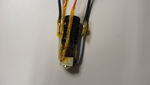
Put the connectors on the motor wires
- solder a female connector to the ends of each wire.
- use the 2.54mm 1x3 housing.
- Shown is the type used for servos in RC projects. See [Stepper Motors] for info on motors.
Thermistor Wires
Use a 2 pin 0.1" connector to terminate the thermistor wires.
- Connect the cable so the 2 wires go to T0
- Connect the 2 heater wires to D10 (E0H on older boards) and the + connection above it.
- If changing to an unverified firmware it is best to verify heater circuit function with a meter before connecting heater to prevent damage to the extruder.
Pololu carriage

This section assumes you are using Pololu, but there are other options. Insert two 1x8 pin headers into the board. If you bought a kit with one 16 pin header, simply cut it so that you have two 1x8. Make sure that the side with the labels has the long ends of the posts, and the side you want to solder is the side with the heat sink. Doing this backwards will cause you not to see the labels and will most likely not fit. Remember to apply a heat-sink to the largest chip on the back.
Wiring
It is relatively simple to wire up the RAMPS. Just add the extruder heating coil wire to D10, the thermistor to the two T0 pins on middle right right, and wire up the steppers and endstops. From left to right, wire all of the stepper motor's wires as red, blue, green, and black or red, green, yellow, blue into the pins next to the Pololus. When you connect the wires to the endstops (if you are using 3 endstops, plug them into the MIN (-) slots), make sure you match the labels.


Note that tesla & tonok firmware use d9 and sprinter and johnny/tonok use d10 for the extruder hot end.
Warnings
Reversing +/- or otherwise incorrectly connecting power can destroy your electronics and cause fire hazard.
Incorrectly inserting stepper drivers will destroy your electronics and cause a fire risk. Always make sure power and USB is disconnected when removing or adjusting stepper drivers. Always make sure to insert drivers in correct orientation and in the socket correctly.
The endstop pins are Signal - GND - VCC, instead of the VCC - Sig - GND like the rest of RepRaps boards. Make sure to wire them correctly. This is done to allow squeezing fatter traces on the printable board.
Connecting Power
Connect your 12V power supply to the RAMPS shield. Reversing +/- or otherwise incorrectly connecting power can destroy your electronics and cause fire hazard.
The bottom pair of connectors marked 5A power the stepper drivers and Extruder heater/fan (D9, D10). The source should be rated a minimum of 5A.
The pair of connectors above marked 11A power a Heated Bed, or other output (D8). The source should be rated a minimum 11A (if both power rails are connected to the same supply it should have a minimum rating of 16A).
The barrel connector, on the Arduino MEGA, will NOT power RAMPS and will not provide power to the stepper motors, heated bed, etc.
The power connector plug may not be obviously labeled, looking at the power connection the positive is on the left and the negative is on the right of the plug.
Power Supply

RAMPS is quite happy with the 12 V line from PCPowerSupply. Or you can hack up a 12V laptop power supply, or other 12 V "wall wart" power supply. Be sure that the power can output 5A or greater. Additional 11A may be needed for heated bed support.
See Connecting power above.
The 3 pins next to the reset switch are meant to optionally connect to your PSU.
The PS_ON pin is intended to switch your power supply on and off. Many firmwares support pulling this pin low with M80 command to turn the power supply on, and M81 to turn it off. This behavior is desired for ATX power supplies and can be modified in firmware to support 5V high power supplies like those borrowed from an Xbox.
Without D1 installed, or when the 12VIN is not connected, the Arduino gets its power from USB. If you want your kit powered without USB connected you need to solder in D1 OR connect VCC to your PSU.
The VCC pin can be connected to your ATX's 5Vsb to continuously power the Arduino from your ATX power supply. You will want to make sure that D1 is not installed or cut out. The Arduino is not designed to be powered directly on the VCC rail and the VIN pin at the same time.
The 5V pin in that connector on RAMPS only supplies the 5V to the auxiliary servo connectors. It is designed so that you can jumper it to the VCC pin and use the Arduino's power supply to supply 5V for extra servos if you are only powered from USB or 5V. Since there is not a lot of extra power from the Arduino's power supply you can connect it directly to your 5V power supply if you have one. You can also leave this pin not connected if you have no plan to add extra servos.
In the case of using an ATX power and who chooses not to use the 3 pins above that Hack will turn on when connected to to the mains. To prepare to see the video tutorial Obijuan: Preparing the power supply.
Maximum Input Voltage
Power Supply without diode
The 1N4004 diode connects the RAMPS input voltage to the MEGA. If your board does not have this diode soldered in, you can safely input as much as 35V. (The pololus can do up to 35V)
Power Supply with diode
If your board has a 1N4004 diode soldered in, do not apply more than 12 V to it. Original flavor Arduino Mega are rated to 12 V input. While Arduino Mega 2560 can take 20 V, it is not recommended.
Calibration Pololu/Stepstick
If you think you may have mistakes you can install only one stepper driver during initial testing and risk only one stepper driver.
The trimpot on the stepper drivers controls the current limit. Turn it all the way down (counter clock wise) and back up 25%. Be careful to not force the trimpot, it is delicate. You will need to fine tune the current limit later. Note that it is allways giving the motors that much power, even when not moving, so if your stepper motor drivers are getting hot, you may want to turn it down slightly.
Connect the minimum endstops for X, Y, and Z.
Connect Motors (Do not disconnect or connect motors while powered; if the connection is loose, this will cause the motors to spazz and possibly kill your stepper driver.)
You may want to use this code to test all the electronics before installing any of the suggested firmwares.
Install firmware. Firmware flashing can be done without 12V power supply connected.
Method A
LEAPto3D manual --> https://docs.google.com/viewer?a=v&pid=forums&srcid=MTEwOTQ1MzA1MzA4MDUwMjA2MDEBMDA2NDE2NDc2MzE1NDk0OTkzNzQBc29HNGxGbDFhaFlKATQBAXYy
Method B
Method Miguel Sánchez (misan). In this way Pololus calibrate the reference is taken as the voltage on the potentiometer, which is a reference voltage for the current control. In Pololus is 0.4V per amp. That tension may be adjusted with the advantage of not having the 12V connected and can do so with all the connected driver at a time. To do this, put the common pin (GND) of the multimeter to the USB enclosure and positive screw regulates the motor current PaP. This regulation is linear, equivalent to 1 ampere 0.4V so 0.1V = 250mA, 0.2V = 500mA.
Recommended values
| Axis | X | Y | Z | Extruder |
| Method A current (mA) | 200 | 200 | 400-500 | 350-500 |
| Method B voltage (V) | 0,08 | 0,08 | 0,16-0,2 | 0,14-0,2 |
Firmware and Software
Firmware
RAMPS 1.4 uses the same pin definitions as 1.3.
You will need the Arduino software at http://www.arduino.cc/en/Main/Software to upload the firmware to Arduino Mega. Arduino MEGA 2560 Rev3 requires Arduino software version 0023.
Sprinter and Marlin are popular and stable firmwares for RAMPS as of 12/28/2012.
Working preconfigured sprinter firmware can be downloaded at http://ultimachine.com/sites/default/files/UltiMachineRAMPS1-4Sprinter.zip . Mechanical is in the folder ending with ME, optical endstop firmware is in the folder ending in OE.
Others (Need pins set in Firmware as below):
- mechanical endstops (now the default ultimachine.com option) require #define OPTO_PULLUPS_INTERNAL 1 to be added to configuration.h if not there by default.
Here are the pin definitions for this board.
// For RAMPS 1.4
#define X_STEP_PIN         54
#define X_DIR_PIN          55
#define X_ENABLE_PIN       38
#define X_MIN_PIN           3
#define X_MAX_PIN           2

#define Y_STEP_PIN         60
#define Y_DIR_PIN          61
#define Y_ENABLE_PIN       56
#define Y_MIN_PIN          14
#define Y_MAX_PIN          15

#define Z_STEP_PIN         46
#define Z_DIR_PIN          48
#define Z_ENABLE_PIN       62
#define Z_MIN_PIN          18
#define Z_MAX_PIN          19

#define E_STEP_PIN         26
#define E_DIR_PIN          28
#define E_ENABLE_PIN       24

#define SDPOWER            -1
#define SDSS               53
#define LED_PIN            13

#define FAN_PIN            9

#define PS_ON_PIN          12
#define KILL_PIN           -1

#define HEATER_0_PIN       10
#define HEATER_1_PIN       8
#define TEMP_0_PIN          13   // ANALOG NUMBERING
#define TEMP_1_PIN          14   // ANALOG NUMBERING
Sprinter
Marlin
Programas de laminado
Convert files .Stl in G-code files.
Skeinforge
Calibration Guide by Santiago López (Darkomen)
Guide by Reclone3d.
Slic3r
Software
Pronterface
A common failure in the program is that when I make the gcode G1 movements, movements are not, to fix check if you are using absolute or relative coordinates. To put relative coordinates, use the command G91.
Cura
Cura is a software that will allow us to convert STL files containing 3D design in our physical parts into one working environment. Configuring Cura by Pablo Murillo
Tips
How to insert/extract filament
- Inserting
- Loose the filament idler springs.
- Insert filament by hand gently, until it cannot move more.
- Set heatcore at extracting temp, that is 185C for PLA and 230C for ABS.
- When temp is reached, push gently by hand filament down until it oozes from the nozzle.
- Tighten idler springs.
- Test extrude from host program.
- Extracting
- Loose the filament idler springs.
- Set heatcore at 150C for ABS, 130C for PLA.
- When temp is reached, pull up the filament with your hand.
- Turn of heatcore immediately
How to change ABS to PLA and vice-versa
- Let's say you print with ABS.
- Set temp to 230C
- Unscrew idler and remove ABS filament (see "insert/remove filament)
- Insert PLA
- Temp is 230C
- Gently push filament until it oozes
- Set temp to pla extrude temp (185C)
- Screw idler and test extrusion
- Let's say you print with PLA.
- Set temp to 185C
- Unscrew idler and remove PLA filament (see "insert/remove filament)
- Insert ABS
- Temp is 230C
- Gently push filament until it oozes
- Screw idler and test extrusion
Pictures

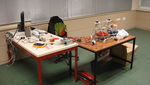
- Desarrollo


Videos
| 300|250</videoflash> |
History
- 11/16/2012: Received printed parts set from multiXtruder
- 11/28/2012: Buyed nut, washer, bolt, grub screw, threaded rod, smooth rod, vinyl tubing, bouncy, clamps, terminals, power supply Tooq 500W, etc..
- 11/03/2012: Received RAPMS 1.4 wiht Clon Mega2560, LCD 20x4, Keypad v1.0, Thermistor 100K, 2x Axial Fan 50x50x12mm 12V, 2m PTFE tubing and Pneufit straight adaptor from Reprapworld.
- 11/05/2012: Received 4x Allegro 4982 with heatsink, Thermistor, Heat Bed MK2, 3x Endstops, 5x Nema17, Jhead Mk V-B, wires, 2x pulleys, 2m timing belts, bearing 608zz and LM8UU, hobbed bolt Hyena, 2x ABS 1kg and PLA 1kg from LEAPto3d.
- 12/07/2012: Received kapton tape from Incopia2.
- 12/08/2012: Rods cut and revise plastic pieces.
- 12/13/2012: Solder Allegro 4982 and embedded nuts.
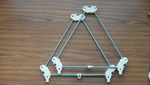
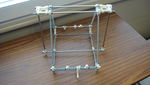
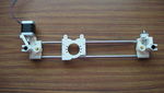
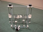
- 12/18/2012: Assembly basic structure, it absence axis X
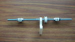
- 12/19/2012: Assembling axis X.
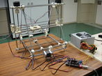
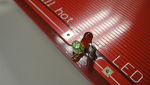
- 12/20/2012: Electronics assembled and tested. Now Playing the Imperial March.
- 01/09/2013: The wood base has been mounted, but the linears bearings are not going well, it seems that moving costs.
- 01/17/2013: Extruder mounted and it seems that a driver is broken.
- 01/18/2013: I redesigned the Z axis, I take up the slack. Loosened belt axis, appears to move with greater speed, but without losing steps. I weld and check the endstop. I calibrate the X and Y axis.
Links
- GitHub Ronquío.
- Virtual clone Pulpo.
- REPRAP.
- RAMPS 1.4.
- The incomplete reprap beginner´s guide.
- Color mixing.
- CAM Toolchains/es.
|
|
Universidad de Jaén |
|
|
RepRap |
|
|
Projetc Clone Wars |