Gen7 Research
|
English • العربية • български • català • čeština • Deutsch • Ελληνικά • español • فارسی • français • hrvatski • magyar • italiano • română • 日本語 • 한국어 • lietuvių • Nederlands • norsk • polski • português • русский • Türkçe • українська • 中文(中国大陆) • 中文(台灣) • עברית • azərbaycanca • |
This page shows some of the research done for developing Generation 7 Electronics. It may be helpful for developing other electronics as well.
Contents
MOSFET heat
With heated beds becoming more and more standard, MOSFETs are used to switch currents in excess of 10 Ampéres, sometimes 15 A. While MOSFETs exist which claim to be capable to switch much higher currents, it has been shown they require a careful integration into the electrical design of the electronics. To get to the bottom of this, I've done a few measurement series', measuring heat development of a MOSFET in different configurations.
Markus "Traumflug" Hitter, February 2012
Test setup
The electronics used to do the tests was an older Gen7 v1.2, which first had to be fixed.
The heated bed were two undersized test beds, soldered together. Together they had a cold resistance of about 1.2 Ohms, requesting about 10 A at 12 V.
The power supply was a generic 250 W PC-PSU, specified for 13 A on the 12 V-Rail.
The MOSFET was equipped with a heatsink made of a flat sheet of painted aluminium to give good exposure for a phyrometer, a touchless thermometer. The contact point between MOSFET and heatsink was carefully cleaned from paint, of course, but no thermal paste was applied. It was taken care to not blow against the heatsink to not falsify temperature measurements.
The cross on the heatsink was a mark to ensure the temperature reading was always taken at the same place. The next picture shows how this was done. The red spot is a pointing laser built into the phyrometer.
As the heated bed was undersized, it gained in excess of 150 °C on first tests and started to fume. So a fan was placed underneath to cool it. The maximum temperature reached was something like 80 °C, but not measured.
The firmware in use was Teacup, configured to accept direct PWM commands. The ATmega's PWM scale reaches from 0 to 255, so for example M104 S20 equals 7.8%, M104 S160 equals 63%.
Overall the test equipment wasn't made of precision instruments, but very well in the range of giving quality and approximated quantity results.

The heat wasting bed.

The heatsink.

Taking a temperature measurement.


Results
To not bore you with long columns of numbers, I've uploaded the spreadsheet used to write all the measurements down on Github. Click on "View Raw", then save it to open it with GNUmeric instead of a text editor.
Common results
While the voltage measured with a simple voltage meter at the heated bed connector varies widely with PWM percentage (this is the whole point of PWM), the voltage always maxed out at about 10.95 Volts, about 1 V below the power supply voltage. This expected and a typical property of voltages goinf through semiconductors.
Each of the charts in the following chapters shows the PWM value on the horizontal axis, bed voltage on the left vertical scale, heatsink temperature on the right one.
Heat vs. PWM Frequency
The MOSFET used was an IRFZ 44N, the current standard of Gen7. The resistor between the ATmega and the MOSFET signal input was 1000 Ohms. The PWM frequency was changed in Teacup between all 5 levels the ATmega offers. The Gen7 is clocked by a 20 MHz crystal, with a 16 MHz crystal you get different frequencies.
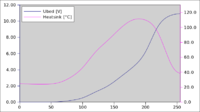
PWM = 78 kHz, Tmax = 110 °C

PWM = 9.8 kHz, Tmax = 50 °C
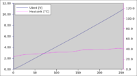
PWM = 1220 Hz, Tmax = 41 °C
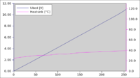
PWM = 305 Hz, Tmax = 39 °C

PWM = 76 Hz, Tmax = 38 °C


One thing which can not be seen in the graphs is, you can hear PWM frequencies in the audible range (20 Hz to 15 kHz) from the power supply and from the heated bed. You have to have a quiet environment to notice this, though, a 12 V fan running calmly on 5 V is louder.
Heat vs. Signal Resistor
The MOSFET used was an IRFZ 44N, the current standard of Gen7. The PWM frequency was 78 kHz in all cases. The resistor between the ATmega and the MOSFET signal input was changed between 1000 Ohms, 180 Ohms, 10 Ohms and 0 Ohms (plain wire).
R = 1000 Ohms, Tmax = 110 °C

R = 180 Ohms, Tmax = 72 °C

R = 10 Ohms, Tmax = 57 °C

R = 0 Ohms, Tmax = 57 °C


Conclusions and Recommendations
This is my (Traumflug's interpretation of the results.
Conclusions
- MOSFETs can heat up considerably if they're integrated poorly into the circuitry and/or are driven with a too high PWM frequency. This is apparently due to losses in the short switching times where the MOSFET is neither fully open nor fully closed.
- MOSFET heat due to constant current flowing is a lot less than that of misconfigured switching.
- Your heater never receives the full power supply voltage.
- PWM frequencies in the hearable range make parts of your setup beep or hum, but this is barely noticeable.
- You can check your MOSFET efficieny without waiting for it to heat up by setting the PWM percentage to 80 of 255 and measuring the voltage on the output. The ideal value (no switching losses) would be
- full open voltage / 255 * 80
- If you get about 90% of the ideal voltage or more, you're sane.
Recommendations
- If your MOSFET gets too hot, the most simple way to deal with this is to reduce PWM frequency.
- The resistor between ATmega and the MOSFET's gate should be 10 Ohms. More increases switching time and thus increases heat, less gives up protection of the ATmega output at no gain.