Gen7 Research
|
English • العربية • български • català • čeština • Deutsch • Ελληνικά • español • فارسی • français • hrvatski • magyar • italiano • română • 日本語 • 한국어 • lietuvių • Nederlands • norsk • polski • português • русский • Türkçe • українська • 中文(中国大陆) • 中文(台灣) • עברית • azərbaycanca • |
This page shows some of the research done for developing Generation 7 Electronics. It may be helpful for developing other electronics as well.
Contents
MOSFET heat and PWM
With heated beds becoming more and more standard, MOSFETs are used to switch currents in excess of 10 Ampéres, sometimes 15 A. While MOSFETs exist which claim to be capable to switch much higher currents, it has been shown they require a careful integration into the electrical design of the electronics. To get to the bottom of this, I've done a few measurement series', measuring heat development of a MOSFET in different configurations.
Markus "Traumflug" Hitter, February 2012
Test setup
The electronics used to do the tests was an older Gen7 v1.2, which first had to be fixed.
The heated bed were two undersized test beds, soldered together. Together they had a cold resistance of about 1.2 Ohms, requesting about 10 A at 12 V.
The power supply was a generic 250 W PC-PSU, specified for 13 A on the 12 V-Rail.
The MOSFET was equipped with a heatsink made of a flat sheet of painted aluminium to give good exposure for a phyrometer, a touchless thermometer. The contact point between MOSFET and heatsink was carefully cleaned from paint, of course, but no thermal paste was applied. It was taken care to not blow against the heatsink to not falsify temperature measurements.
The cross on the heatsink was a mark to ensure the temperature reading was always taken at the same place. The next picture shows how this was done. The red spot is a pointing laser built into the phyrometer.
As the heated bed was undersized, it gained in excess of 150 °C on first tests and started to fume. So a fan was placed underneath to cool it. The maximum temperature reached was something like 80 °C, but not measured.
The firmware in use was Teacup, configured to accept direct PWM commands. The ATmega's PWM scale reaches from 0 to 255, so for example M104 S20 equals 7.8%, M104 S160 equals 63%.
Overall the test equipment wasn't made of precision instruments, but very well in the range of giving qualitative and approximated quantitative results.

The heat wasting bed.

The heatsink.

Taking a temperature measurement.


Results
To not bore you with long columns of numbers, I've uploaded the spreadsheet used to write all the measurements down on Github. Click on "View Raw", then save it to open it with GNUmeric instead of a text editor.
Common results
While the voltage measured with a simple voltage meter at the heated bed connector varies widely with PWM percentage (this is the whole point of PWM), the voltage always maxed out at about 10.95 Volts, about 1 V below the power supply voltage. This expected and a typical property of voltages goinf through semiconductors.
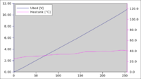
Each of the charts in the following chapters shows the PWM value on the horizontal axis, bed voltage on the left vertical scale, heatsink temperature on the right one.
Heat vs. PWM Frequency
The MOSFET used was an IRFZ 44N, the current standard of Gen7. The resistor between the ATmega and the MOSFET signal input was 1000 Ohms. The PWM frequency was changed in Teacup between all 5 levels the ATmega offers. The Gen7 is clocked by a 20 MHz crystal, with a 16 MHz crystal you get different frequencies.
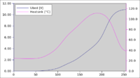
PWM = 78 kHz, Tmax = 110 °C

PWM = 9.8 kHz, Tmax = 50 °C
PWM = 1220 Hz, Tmax = 41 °C
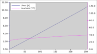
PWM = 305 Hz, Tmax = 39 °C

PWM = 76 Hz, Tmax = 38 °C


One thing which can not be seen in the graphs is, you can hear PWM frequencies in the audible range (20 Hz to 15 kHz) from the power supply and from the heated bed. You have to have a quiet environment to notice this, though, a 12 V fan running calmly on 5 V is louder.
Heat vs. Signal Resistor
The MOSFET used was an IRFZ 44N, the current standard of Gen7. The PWM frequency was 78 kHz in all cases. The resistor between the ATmega and the MOSFET signal input was changed between 1000 Ohms, 180 Ohms, 10 Ohms and 0 Ohms (plain wire).
R = 1000 Ohms, Tmax = 110 °C

R = 180 Ohms, Tmax = 72 °C

R = 10 Ohms, Tmax = 57 °C

R = 0 Ohms, Tmax = 57 °C


Cyberwizzard did similar tests and described his findings in a forum post.
Conclusions and Recommendations
This is my (Traumflug's) interpretation of the results.
Conclusions
- MOSFETs can heat up considerably if they're integrated poorly into the circuitry and/or are driven with a too high PWM frequency. This is apparently due to losses in the short switching times where the MOSFET is neither fully open nor fully closed.
- MOSFET heat due to constant current flowing is a lot less than that of misconfigured switching.
- Your heater never receives the full power supply voltage.
- PWM frequencies in the hearable range make parts of your setup beep or hum, but this is barely noticeable.
- You can check your MOSFET efficieny without waiting for it to heat up by setting the PWM percentage to 80 of 255 and measuring the voltage on the output. The ideal value (no switching losses) would be
- full open voltage / 255 * 80
- If you get about 90% of the ideal voltage or more, you're sane.
Recommendations
- If your MOSFET gets too hot, the most simple way to deal with this is to reduce PWM frequency.
- The resistor between ATmega and the MOSFET's gate should be 10 Ohms. More increases switching time and thus increases heat, less gives up protection of the ATmega output at no gain.
MOSFET Heat and MOSFET Type
By Markus " Traumflug" Hitter in August 2012.
Even more obvious than with the previous research, the heat developed by the MOSFET depends much on the type of MOSFET in use. Many recommendations float around in the RepRap community, so I picked the most promising samples and tested them. These were (click on the name for a data sheet):
- IRFZ 44N, the one recommended for Gen7 v1.4 and before.
- IRLZ 34N, a similar type with lower gate voltage requirements.
- IRL 3803
- FDP 8870, recommended on IRC.
- IRLB 8743, also recommended on IRC, now choosen for Gen7.
As some voices suggest MOSFETs vary significantly from individual piece to piece, two samples of each were tested, totalling to a series of 10 runs.
Characteristic Data
Here are some numbers, fetched form the data sheets, which may help to view the differences between all these.
- ID is usually seen in Fig. 9 at 25 °C package temperature.
- RDS(on) is usually seen in Fig. 1 at a gate voltage of 5 V, calculate R = U / I in the straight raising part of the curve.
- Gate Charge can usually be found in Fig. 6, at VDS closest to 12 V and VGS = 5 V.
- "Miller" can be seen in Fig. 6, too, and is the gate-source voltage where the flat part of the charge curve happens (above that the "Miller"-effect starts). This may give an indication of the minimum voltage required to drive that MOSFET.
| ID | RDS(on) | Rise Time | Fall Time | Gate Charge | Miller | |
|---|---|---|---|---|---|---|
| IRFZ 44N | 48 A | 31 mΩ | 60 ns | 45 ns | 22 nC | 5.1 V |
| IRLZ 34N | 30 A | 43 mΩ | 100 ns | 29 ns | 14 nC | 3.6 V |
| IRL 3803 | 140 A | 9.5 mΩ | 230 ns | 35 ns | 90 nC | 3.7 V |
| FDP 8870 | 156 A | 3.6 mΩ | 105 ns | 46 ns | 30 nC | 3.2 V |
| IRLB 8743 | 155 A | 3.6 mΩ | 92 ns | 36 ns | 38 nC | 3.3 V |
Test Setup
A Gen7 v1.4 was configured pretty much in standard configuration with Teacup firmware. The heated bed was configured to have no thermistor, but TT_NONE instead. This way, Teacup allows to set the PWM value directly. Resistor between MOSFET gate and ATmega was 10 Ω, PWM frequency about 78 kHz. Voltage on the 5 V rail, which switches the MOSFETs, was measured to be 5.20 volts.
The extruder thermistor was glued onto a chopped heatsink with Kapton tape. This allowed to change the MOSFET underneath without too much hassle. Nicely, this also allowed the controller to measure and report it's own MOSFET temperature. At least approximately, as the thermistor setup was uncalibrated.
The load was similar to a heated bed and had a resistance of approximately 1.4 Ω
While the test were meant to run in silent air, the nearby heated bed had to be cooled by a fan, so small amounts of air flow may have reached the MOSFET.
Here are some pictures:

This is an overview of the setup used. Gen7 to the right, heated bed with fan underneath to the left.

My collection of MOSFETs :-)

The chopped heatsink used for measuring the MOSFET temperature.
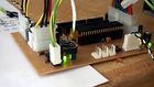
A closer look at the board, showing how the heatsink is mounted.


Note: the absolute results are not comparable to the measurements of the previous series or to a Gen7 in standard configuration, as the heatsink's surface is existent, but much smaller than that of a usual one.
Test Runs
Each test run was 5 Minutes on each of 100/255, 180/255, 200/255 and 255/255 PWM, so a total of 20 minutes. The results were recorded with a serial terminal. To set the PWM values and trigger the temperature reports, the following script was used:
#!/bin/bash

DEV=/dev/ttyACM1

trap 'echo M140 S0 >${DEV}' EXIT

function minutes() {
  COUNTER=60  # 5 minutes
  while [ ${COUNTER} -gt 0 ]; do
    echo M105 >${DEV}
    let COUNTER=${COUNTER}-1
    sleep 5
  done
}

echo M140 S100
echo M140 S100 >${DEV}
minutes
echo M140 S180
echo M140 S180 >${DEV}
minutes
echo M140 S200
echo M140 S200 >${DEV}
minutes
echo M140 S255
echo M140 S255 >${DEV}
minutes
echo M140 S0
echo M140 S0   >${DEV}
Test results
The test results in raw numbers can be found in the Gen7 repository (click on "view raw"). Also inside this spreadsheet file, there are diagrams visualizing these numbers.
Here's the one for high frequency, 78 kHz:

And this one is for low frequency, 76 Hz:

Interpretation
- Yes, apparently different MOSFETs of the same type develop different amounts of heat. In a range of about 10%.
- "Small" MOSFETs develop substantially less heat at low PWM values.
- High frequency PWM is a burden for all MOSFETs. Even more for the "big" ones. Note: none of the RepRap electronics uses a MOSFET driver, apparently for cost/complexity reasons.
- In the mid-to-high PWM range (180/255 to 200/255) at 78 kHz, differences between types are at a minimum.
- "Big" (and more expensive) MOSFETs have an advantage in the "full throttle" mode (always on) or low frequency PWM mode, only.
- Apparently, rise time and fall time have much more influence in heat development when using high-frequency PWM than any other specification item.
- Low frequency PWM or even a bang-bang strategy is advised.
- The "big" types qualify for "barely warm to the touch when switching 10 A" when driven at a low PWM frequency.
No ideal, high-frequency-PWM, heatsink-free, bullet-proof solution in sight. However, demanding a low PWM frequency isn't asking too much. The humming is hearable in a quiet environment only and firmware configuration templates can make this mode the default, so burnt MOSFETs due to high-frequency switching losses should be rare.
Nevertheless, a "big" MOSFET with low RDS(on) value when used on a heat bed, will run considerably cooler as for most of the time the PWM runs at 100% and the MOSFET is full on. When I changed the default ver 1.3.1 MOSFET IRFZ44N with an IRF3703 with RDS(on) around 3-4mΩ , the new MOSFET temperature never exeeded 45C even with a very small heatsink, while with the IRFZ44N a big 10x5cm heatsink was needed and even then, temperatures of 100C-120C were experienced on the MOSFET. So for whomever still has the IRFZ44N as a heatbed switching MOSFET and experiences issues with high MOSFET temperatures, I would advise her to switch to IRLB 8743 (gen7 ver 1.4.1 suggestion) , IRF 3703, or any other MOSFET with a considerably low RDS(on)
Further Reading
Basics about switching loads with MOSFETs, a theory based approach to the matter.
MOSFET Heat by Math
One can calculate a good estimate of the resulting temperature purely by data sheet and math. From the data sheet we need RDS(on) and Thermal Resistance Junction to Ambient, RJA. Then math is simple: Heat development:
- <math>P = I^2 * R_{DS(on)}</math>
For an IRLB 8743 at 4.5 V signal and 10 A, that's:
- <math>P = 10^2\,A^2 * 0.0035\,\Omega = 0.35\,W</math>
Now simply multiply this with RJA, add ambient temperature and there you go:
- <math>T = P * R_{JA} + T_{Room} = 0.35\,W * 62\,°C/W + 22\,°C = 43.7\,°C</math>
Pretty consistent with the above measurements, a bit on the safe side. That's good!
To get a better idea what RDS(on) is on non-standard signal voltages, there's usually a graph in the data sheet which shows Drain-to-Source current over Drain-to-Source voltage for many signal voltages. Pick the spot where the signal voltage curve crosses the expected current (ID). Then you can calculate RDS(on):
- <math>R_{DS(on)} = V_{DS} / I_D</math>
In the IRLB 8743 data sheet, 15 A is outside the graph for most signal voltages, so you have to extrapolate a bit.
Selecting the Thermistor Voltage Divider
- main article: Thermistor
By Markus " Traumflug" Hitter in November 2012.
When reviewing each part of the AVR Gen7 circuitry (running on 5 V) for compliance with the ARM variant (running on 3.3 V) I also came across the thermistor part. Like in about any RepRap electronics, Gen7 makes up a voltage divider with the thermistor and a fixed value resistor. Usually, this fixed resistor is 4.7 kΩ.
With formulas given in the Hydraraptor blog and in textbooks, one can calculate precise numbers. After a lot of typing, however, I decided to put all this into a spreadsheet. Not only for saving the keyboard of my pocket calculator, also for getting some graphs.
The goal of all this thermistor business is to get a voltage which has a known relation to the temperature of the thermistor and can be measured by the analog-to-digital converters of our microprocessors. As thermistors are highly non-linear, the voltage divider was put into place to get a much higher resolution (voltage change per temperature change) at the temperature of interest.
The current situation
As far as I can see, all RepRap controller circuitries share the same design for the thermistor circuitry, all agree on a thermistor with 100 kΩ resistance at 25 °C and also on a fixed resistor of 4.7 kΩ. Given this, we get the following situation:

You see the blue line, which shows the resistance of the thermistor depending on its temperature. The corresponding scale is on the left side. Knowing this, one can calculate the voltage on the microcontoller's pin (green line, scale to the right).
The interesting part is the pink line. The higher the pink line, the higher the voltage change per temperature change. Ideally, the pink line has it's top at the temperature we're interested in. As we can see, the actual optimum is at 100 °C (vertical black line). Looking at typical extruder temperatures, the pink line is very, very low. Not exactly an ideal situation.
Improving the situation
Warning: this ignores thermistor self heating. I ran some quick numbers and lowering the fixed resistors value to 560 will cause the thermistor to heat itself signifcantly, up to 8 deg C at 100, all the way to 27 deg C at 220! The default 4.7K resistor only heats 3.3 and .9 deg C at those temperatures, respectivly. I was in the middle of ordering the parts he mentioned here to apply this improvment to my machine, and had a thought to check the numbers and this is what i found.
- Good catch! It would be a nice improvement if you could add the self-heating to the spreadsheet. --Traumflug 12:14, 4 June 2013 (UTC)
Spreadsheets with graphs invite to play a bit with the numbers, so I did that. Much more fun than stepping through complex formulas (which I did as well, but found to be too complex to explain this here) and simply look what happens.
- Change the supply voltage: no change of the graph, just the scale is different.
- Change the thermistor type from 100k to 10k: the pink curve moves a lot to the left, making things worse.
- Change the fixed resistor: Oh!

As you can see, one can use the value of the fixed resistor to vary the temperature optimum of the circuitry widely. A lower resistor moves the optimum to a higher temperature range. So I moved down: 4k7, 2k2, 1k, 560, 180 ... all values I have available because they're used elsewhere on the Gen7 board already. 180 was a bit much, but 560 ... With an 560 Ω voltage divider resistor the optimum temperature is at 185 °C (excellent for PLA) and the pink line is about 5 times higher at 260 °C, the typical ABS extruding temperature, than with the commonly used 4.7 kΩ. Exciting improvement with such a simple change!
So, all I can recommend is to play around yourself, the Thermistor Playground (click on "view raw") can be found in the Generation 7 Electronics Github repository. There's only one table in the Playground and the four input values are those to the right of the bolded text.