Thermistor
|
English • العربية • български • català • čeština • Deutsch • Ελληνικά • español • فارسی • français • hrvatski • magyar • italiano • română • 日本語 • 한국어 • lietuvių • Nederlands • norsk • polski • português • русский • Türkçe • українська • 中文(中国大陆) • 中文(台灣) • עברית • azərbaycanca • |
Vitamin
| A Thermistor is the most commonly used temperature sensor in RepRap printers. | |
| Wikipedia | Thermistor |
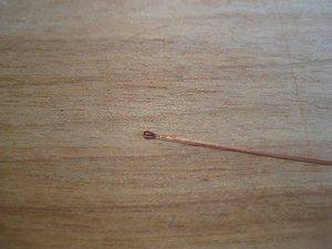
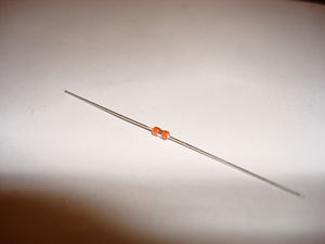
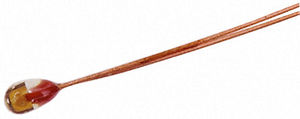
In most RepRaps, a thermistor senses the temperature of the Hot End. Often a second thermistor senses the temperature of the Heated Bed.
Thermistors are resistors that change of resistance with a change in temperature. Good qualities of thermistors are a predictable, accurately known resistance value at every temperature in its operating range. The lowering, or rise, depends on the type of thermistor per degree Kelvin (or Celcius, if you prefer), this is called its coefficient. Positive thermal coefficient (PTC) will increase in resistance with an increase in temperature, negative ones (NTC) will decrease. But the formula in practice is not linear, so sometimes an accurate table of measurements is better than the linear formula. These measurements can usually be found in the datasheet that accompanies the thermistor.
Contents
- 1 Theory
- 2 Troubleshooting
- 3 Thermistors vs thermocouples
- 4 RTD
- 5 RepRap Thermistors
- 5.1 See also
- 5.2 EPCOS 100K Thermistor (B57540G0104F000)
- 5.3 EPCOS 100K Thermistor (B57560G1104F)
- 5.4 EPCOS 100K Thermistor (B57560G104F)
- 5.5 RRRF 100K Thermistor
- 5.6 RRRF 10K Thermistor
- 5.7 RS 10K Thermistor
- 5.8 Honeywell 100K Thermistor (135-104LAG-J01)
- 5.9 Honeywell 500K Thermistor (135-504QAG-J01)
- 5.10 ATC Semitec 104GT-2
- 5.11 PT1000 (Cyntec - same for other suppliers???) (1kOhm)
- 5.12 KTY82-210 (Philips) (2kOhm SMD)
- 6 Thermistor Calculations
- 7 Further reading
Theory
You cannot directly measure resistance. To test the resistance, you can put a voltage on a wire and see how much current will run. Another alternative is to use it together with another resistor of a known value, and measure the potential (or voltage) between the resistors. This is what a multimeter does to be able to show you the (deduced) resistance. Remember that there usually is a dial on a multimeter, this allows you to select a range to measure in. This is because the value of the known resistor has to be varied to have the potential (voltage) be in a range that can be measured accurately.
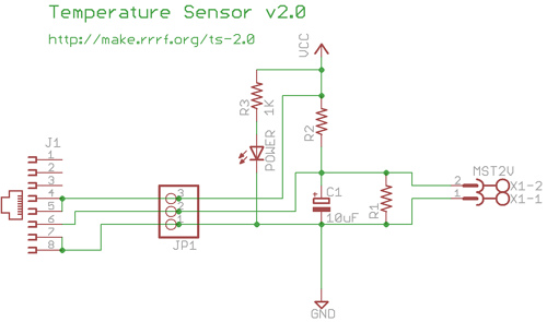
This can best be explained by example: You have two resistors between 0 and 5V. The two resistors are R2=4.7K Ohm at the 5V side and R1=1K Ohm at the ground side. The two resistors act as what is known as a voltage divider. Between the resistors, the voltage is based on the ratio of the two resistances. If you have the 5V power source (Vcc) turned on, this means that the voltage will be: 5V - 5V * 4700/(4700+1000) = ~ 0.88 V. This is also the voltage you would measure at the R2 + R1 junction with a multimeter/voltmeter. If you add a resistor to the mix that changes strongly with a change in temperature, this will affect the value of the voltage divider and the resulting voltage in between. This is because two parallel resistors of which one changes resistance, the total resistance of the total resistance will change as well.
If the thermistor Rth is connected between the ground (0 Volts) and the middle of the two resistors, the value of resistance between the middle junction and the ground will be based on the following formula:
Rpair = 1 / (1/R1 + 1/Rth) = 1 / (1/1000 + 1/Rth) = Rpair
Rpair is the resistance between 0 V and the middle junction. If Rpair is known, based on the calculation of the voltage divider, you can deduce the resistance of the thermistor (Rth).
Through algebraic manipulation you get the formula for Rth: Rth = 1 / (1/1000 - 1/Rpair)
In voltage terms, the voltage at the junction Vout is:
Vout = Vcc*Rpair/(R2+Rpair)
The ADC in reprap hardware measures Vout as the fractional voltage between its reference voltage Vref (commonly Vref=Vcc) and 0V, expressed as a count of steps (commonly 0 to 1023) at the resolution of the ADC (commonly 1024 or 10 bits.)
As a ratio, the voltage difference is:
Vout/Vcc = Rpair/(R2+Rpair)
As a ADC count, the ADC produces:
ADC_count = 1024*Vout/Vref = 1024*Rpair/(R2+Rpair)
ADC_count is limited to the range (0,...,1023) and the device may be damaged with Vout below 0 or above Vref.
Reprap firmware typically uses a table of values mapping an ADC voltage count to a temperature in Celcius (see example below). One could create this table manually by measuring the temperature of the sensor and reading the count from the ADC, or by measuring the temperatures and corresponding voltages (Vout) and calculating the 1024*Vout/Vref, or one could use a program to do these calculations for you.
Note that the tables below refer to a broken link, and that the tables were likely generated with a modified copy of createTemperatureLookup.py.
Note also that several of the tables below for 100Kohm thermistors indicate a R1=0, which, to the createTemperatureLookup.py program, indicates a non-existent R1 (R1 is an open circuit or an infinite resistance). The higher resistance thermistors do not commonly require an R1 to be stable at the operating temperatures. A non existent R1 simplifies the above equations in that Rpair = Rtherm, and the basic ADC count as read by the electronics is:
ADC_count = 1024*Vout/Vref = 1024* Rth /(R2+Rth) # for 100K thermistors without R1.
I suspect the best resistor selection -- given some thermistor, the resistor values that give the best sensitivity to temperature at some desired temperature -- is to choose R2 the same resistance as the thermistor at the desired temperature, and to leave out R1 ("infinity"). (In other words, R2 is *not* the room-temperature resistance of the thermistor, unless you really want to optimize for room temperature). Given the desired temperature Td and a nearby temperature Td + 1 Kelvin, those resistor values are the ones that give the greatest difference in output voltage between those temperatures. I thought that would imply that the maximum in the pink graphs on the Gen7 Research#Selecting the Thermistor Voltage Divider page would occur at exactly the point where the output voltage (the green graph) crossed half the supply voltage. I see that the maximum of the pink graph is very close to, but not exactly equal to that half-way point -- am I reading the graphs incorrectly, or is my intuition a bit off? --DavidCary (talk) 11:32, 3 March 2014 (PST)
Troubleshooting
Thermistors used in RepRap machines are typically 100Kohm at 25C Negative Temperature Coefficient (NTC) temperature sensitive resistors. Basic troubleshooting of a thermistor is to measure its resistance at room temperature, and compare it to the rated 100K resistance. If it is significantly smaller there may be some sort of short. If significantly larger, it make be an open circuit.
The various Electronics translate the resistance into a voltage through a voltage dividing circuit, while the firmware translates the voltage measured by in ADC counts into a temperature using a thermistor table (e.g.: https://github.com/ErikZalm/Marlin/blob/Marlin_v1/Marlin/thermistortables.h )
The values reported by the software are constrained to the values in the thermistor table, so an unusually large temperature that matches the highest temperature in the table indicates an open circuit, or unconnected thermistor. An unusually low value that matches the lowest temperature in the table indicates a shorted thermistor.
Thermistors vs thermocouples
- main article: Thermocouple vs Thermistor.
A thermistor is usually more accurate than a thermocouple, but thermocouples can handle higher temperatures and are linear. A thermocouple gives a really small voltage (Type K produces 8.138mV @200C) that can be calibrated and conditioned by an IC (AD595A Amplifier, MAX6675 SPI, or MAX31855 SPI) into a form readable by the electronics. Thermocouples can be more sensitive to noise because of the low voltage. The thermocouple is technically the junction between the two wires so the measurement area and form factor are smaller.
RTD
A resistance temperature detector (RTD) differs from a thermistor in that the temperature-sensitive material used in a thermistor is generally a ceramic or polymer, while RTDs use pure metals. Both of them measure temperature by its effect on the resistance of the sensor. RTDs are useful over larger temperature ranges, while thermistors typically achieve a higher precision within a limited temperature range. (Wikipedia: resistance thermometer).
The "RTD Temperature sensor module" shows how some people read temperatures from a RTD with an Arduino. "RTD PT1000 circuits" has a few more comments.
RepRap forum: "thermistor/thermocouple for BfB extruder with PIC electronics?" and "Duet - Arduino Due Compatible 3D Printer Electronics" briefly discusses RTDs.
Do RTDs have any advantages or disadvantages for 3D printing compared to thermistors or thermocouples?
RepRap Thermistors
A variety of thermistors you may encounter when building a RepRap are listed below, along with the most important information about the thermistor:
- manufacturer and manufacturer's part number -- which thermistor are we talking about?
- manufacturer's datasheet
- Operating Temperature Range -- can it handle the 260 °C used to test hotend theory?
- Rn @ Tn (typically 100 KOhms @ 25 °C) -- the nominal resistance at the nominal test temperature, typically room temperature.
- Beta (typically around 4000 Kelvin) is a material property that describes the best way to fit the standard curve through the actual resistance-vs-temperature data. (Because the fit is not an exact match, some manufacturers publish several slightly different Beta values -- a "B_0/100" value that gives an adequate fit over the entire 0 C to 100 C range, and a "B_25/85" value for the same thermistor that has less error over 25 C to 85 C but has worse error outside that range).
- A table of ADC counts vs. temperature (Celcius) calculated from the above Rn @ Tn and Beta values (and external R1 R2 resistor values).
- Rz -- the nominal resistance at zero °C. Talk: Thermistor#Does anyone ever use the Rz value?
- R(230°C) -- roughly the resistance when printing ABS or PLA
These tables were calculated using this Python script. The resistors are labeled as in Temperature_Sensor_2_0#Schematic, shown on the right.
EPCOS also has data for R/T curves for all of their products in this web-utility.
One of the earliest RepRaps happened to use a "100 kΩ Epcos thermistor" ("#1 in most firmware thermistor tables"[1]). Is that the B57540G0104F000 or is that the B57540G1104F000 or the B57560G104F or the B57560G1104F ? They all have exactly the same Rn @ Tn -- 100 kΩ at 25 °C -- and approximately the same B -- 4036 K to 4092 K ...
Which is the "100k Epcos thermistor" that is #6 in most firmware tables?
See also
For comparison to thermocouples see Thermocouple vs Thermistor.
EPCOS 100K Thermistor (B57540G0104F000)
| Supplier | Part Number |
| Digi-Key | 495-2125-ND |
| Mouser | 871-B57540G104F |
- Rz: 348394
- Temperature rating: -55 degC ~ +250 degC (according to datasheet)
- the datasheet has a nice table of resistance vs. temperature from -55 °C to +250 °C on p. 39 - 40.
- Rn @ Tn: 100 kΩ at 25 °C (indicated by the "104" in the part number, p. 3 of the datasheet)
- B25/85: 4066 K; B25/100: 4085 K (p. 3 of the datasheet)
- 1% tolerance
(Apparently the same as EPCOS B57540G1104F000 ?
See the B57540G1104 datasheet
)
// EPCOS 100K Thermistor (B57540G0104F000)
// Thermistor lookup table for RepRap Temperature Sensor Boards (http://make.rrrf.org/ts)
// Made with createTemperatureLookup.py (http://svn.reprap.org/trunk/reprap/firmware/Arduino/utilities/createTemperatureLookup.py)
// ./createTemperatureLookup.py --r0=100000 --t0=25 --r1=0 --r2=4700 --beta=4066 --max-adc=1023
// r0: 100000
// t0: 25
// r1: 0
// r2: 4700
// beta: 4066
// max adc: 1023
#define NUMTEMPS 20
short temptable[NUMTEMPS][2] = {
   {1, 841},
   {54, 255},
   {107, 209},
   {160, 184},
   {213, 166},
   {266, 153},
   {319, 142},
   {372, 132},
   {425, 124},
   {478, 116},
   {531, 108},
   {584, 101},
   {637, 93},
   {690, 86},
   {743, 78},
   {796, 70},
   {849, 61},
   {902, 50},
   {955, 34},
   {1008, 3}
};
EPCOS 100K Thermistor (B57560G1104F)
| Supplier | Part Number |
| Farnell | 1791917 |
| Mouser | 871-B57560G1104F000 |
- Temperature rating: -55 degC ~ +300 degC ((according to the datasheet)
- B25/85: 4072 K; B25/100: 4092 K
// EPCOS 100K Thermistor (B57560G1104F)
// Made with createTemperatureLookup.py (http://svn.reprap.org/trunk/reprap/firmware/Arduino/utilities/createTemperatureLookup.py)
// ./createTemperatureLookup.py --r0=100000 --t0=25 --r1=0 --r2=4700 --beta=4092 --max-adc=1023
// r0: 100000
// t0: 25
// r1: 0
// r2: 4700
// beta: 4092
// max adc: 1023
#define NUMTEMPS 20
short temptable[NUMTEMPS][2] = {
   {1, 821},
   {54, 252},
   {107, 207},
   {160, 182},
   {213, 165},
   {266, 152},
   {319, 141},
   {372, 131},
   {425, 123},
   {478, 115},
   {531, 107},
   {584, 100},
   {637, 93},
   {690, 86},
   {743, 78},
   {796, 70},
   {849, 60},
   {902, 49},
   {955, 34},
   {1008, 3}
};
EPCOS 100K Thermistor (B57560G104F)
| Supplier | Part Number |
| Farnell | 3878697 |
Obsolete - not recommended for new designs (NRND). Substitute: B57560G1104
// EPCOS 100K Thermistor #3(B57560G104F)
// Made with createTemperatureLookup.py (http://svn.reprap.org/trunk/reprap/firmware/Arduino/utilities/createTemperatureLookup.py)
// ./createTemperatureLookup.py --r0=100000 --t0=25 --r1=0 --r2=4700 --beta=4036 --max-adc=1023
// r0: 100000
// t0: 25
// r1: 0
// r2: 4700
// beta: 4036
// max adc: 1023
#define NUMTEMPS 20
// {ADC, temp }, // temp
uint16_t temptable[NUMTEMPS][2] PROGMEM = {
   {1, 864}, // 864.165363324 C
   {54, 258}, // 258.53991594 C
   {107, 211}, // 211.310066205 C
   {160, 185}, // 185.861725716 C
   {213, 168}, // 168.31793816 C
   {266, 154}, // 154.754297589 C
   {319, 143}, // 143.52544406 C
   {372, 133}, // 133.784751118 C
   {425, 125}, // 125.033500921 C
   {478, 116}, // 116.945124847 C
   {531, 109}, // 109.283980973 C
   {584, 101}, // 101.861768746 C
   {637, 94}, // 94.5095302806 C
   {690, 87}, // 87.0542728805 C
   {743, 79}, // 79.2915563492 C
   {796, 70}, // 70.9409729952 C
   {849, 61}, // 61.5523326183 C
   {902, 50}, // 50.25271896 C
   {955, 34}, // 34.7815846664 C
   {1008, 2} // 2.86606331838 C
};
RRRF 100K Thermistor
| Supplier | Part Number |
| RS | 198-961 |
- Rz: 337254
// Thermistor lookup table for RepRap Temperature Sensor Boards (http://make.rrrf.org/ts)
// Made with createTemperatureLookup.py (http://svn.reprap.org/trunk/reprap/firmware/Arduino/utilities/createTemperatureLookup.py)
// ./createTemperatureLookup.py --r0=100000 --t0=25 --r1=0 --r2=4700 --beta=3960 --max-adc=1023
// r0: 100000
// t0: 25
// r1: 0
// r2: 4700
// beta: 3960
// max adc: 1023
#define NUMTEMPS 20
short temptable[NUMTEMPS][2] = {
   {1, 929},
   {54, 266},
   {107, 217},
   {160, 190},
   {213, 172},
   {266, 158},
   {319, 146},
   {372, 136},
   {425, 127},
   {478, 119},
   {531, 111},
   {584, 103},
   {637, 96},
   {690, 88},
   {743, 80},
   {796, 71},
   {849, 62},
   {902, 50},
   {955, 34},
   {1008, 2}
};
RRRF 10K Thermistor
- Rz: 29000
// Thermistor lookup table for RepRap Temperature Sensor Boards (http://make.rrrf.org/ts)
// Made with createTemperatureLookup.py (http://svn.reprap.org/trunk/reprap/firmware/Arduino/utilities/createTemperatureLookup.py)
// ./createTemperatureLookup.py --r0=10000 --t0=25 --r1=680 --r2=1600 --beta=3964 --max-adc=305
// r0: 10000
// t0: 25
// r1: 680
// r2: 1600
// beta: 3964
// max adc: 305
#define NUMTEMPS 19
short temptable[NUMTEMPS][2] = {
   {1, 601},
   {17, 260},
   {33, 213},
   {49, 187},
   {65, 170},
   {81, 156},
   {97, 144},
   {113, 134},
   {129, 125},
   {145, 117},
   {161, 109},
   {177, 101},
   {193, 94},
   {209, 86},
   {225, 78},
   {241, 69},
   {257, 59},
   {273, 46},
   {289, 28}
};
RS 10K Thermistor
- Beta: 3480
- Rz: 29000
// Thermistor lookup table for RepRap Temperature Sensor Boards (http://make.rrrf.org/ts)
// Made with createTemperatureLookup.py (http://svn.reprap.org/trunk/reprap/firmware/Arduino/utilities/createTemperatureLookup.py)
// ./createTemperatureLookup.py --r0=10000 --t0=25 --r1=680 --r2=1600 --beta=3480 --max-adc=315
// r0: 10000
// t0: 25
// r1: 680
// r2: 1600
// beta: 3480
// max adc: 315
#define NUMTEMPS 20
short temptable[NUMTEMPS][2] = {
   {1, 922},
   {17, 327},
   {33, 260},
   {49, 225},
   {65, 202},
   {81, 184},
   {97, 169},
   {113, 156},
   {129, 145},
   {145, 134},
   {161, 125},
   {177, 115},
   {193, 106},
   {209, 96},
   {225, 87},
   {241, 76},
   {257, 64},
   {273, 50},
   {289, 29},
   {305, -45}
};
Honeywell 100K Thermistor (135-104LAG-J01)
| Supplier | Part Number |
| Farnell | 1383986 |
| Mouser | 785-135-104LAG-J01 |
| RS | 2508333162 |
| Digi-Key | 480-3135-ND |
- Temperature rating: -60 °C ~ +300 °C
- (datasheet?)
- beta25/85: 3974 K -- from Specs page
- beta0/50 °C: 3887 K ± 51 K -- from "Resistance-Temperature Conversion Table No. 16"
- 10% tolerance (from Specs page)
- #7 in most firmware tables
// Honeywell 100K Thermistor (135-104LAG-J01)
// Made with createTemperatureLookup.py (http://svn.reprap.org/trunk/reprap/firmware/Arduino/utilities/createTemperatureLookup.py)
// ./createTemperatureLookup.py --r0=100000 --t0=25 --r1=0 --r2=4700 --beta=3974 --max-adc=1023
// r0: 100000
// t0: 25
// r1: 0
// r2: 4700
// beta: 3974
// max adc: 1023
#define NUMTEMPS 20
short temptable[NUMTEMPS][2] = {
{1, 916},
{54, 265},
{107, 216},
{160, 189},
{213, 171},
{266, 157},
{319, 146},
{372, 136},
{425, 127},
{478, 118},
{531, 110},
{584, 103},
{637, 95},
{690, 88},
{743, 80},
{796, 71},
{849, 62},
{902, 50},
{955, 34},
{1008, 2}
};
Honeywell 500K Thermistor (135-504QAG-J01)
| Supplier | Part Number |
| Farnell | |
| Mouser | |
| Digi-Key |
- Temperature rating: -60 °C ~ +300 °C
- (datasheet?)
- beta25/85: 4261 K -- from Specs page
- beta0/50 °C: 4138 K ± 86 K -- from "Resistance-Temperature Conversion Table No. 1"
- 10% tolerance (from Specs page)
ATC Semitec 104GT-2
| Supplier | Part Number |
| Rapid Electronics | 61-0452 |
| Mouser | 104GT-2 obsolete; substitute: 104NT-4-R025H42G |
// /usr/local/bin/createTemperatureLookup.py --r0=100000 --t0=25 --r1=0 --r2=4700 --beta=4267 --max-adc=1023
// r0: 100000
// t0: 25
// r1: 0
// r2: 4700
// beta: 4267
// max adc: 1023
#define NUMTEMPS 20
short temptable[NUMTEMPS][2] = {
   {1, 713},
   {54, 236},
   {107, 195},
   {160, 172},
   {213, 157},
   {266, 144},
   {319, 134},
   {372, 125},
   {425, 117},
   {478, 110},
   {531, 103},
   {584, 96},
   {637, 89},
   {690, 83},
   {743, 75},
   {796, 68},
   {849, 59},
   {902, 48},
   {955, 34},
   {1008, 3}
};
PT1000 (Cyntec - same for other suppliers???) (1kOhm)
Requires modification of board and disconnecting voltage from Vref pin of CPU and adding 100nF capacitor instead. Vref = 1,1V is available internally in CPU. Advantages are good availability and extreme temperature range (more than 500C) and is fairly linear and quite accurate.
r2 = 8k2
Vref = 1,1V
#define NUMTEMPS 15
short temptable[NUMTEMPS][2] = {
   {505, 0},
   {547, 25},
   {591, 50},
   {632, 75},
   {672, 100},
   {711, 125},
   {749, 150},
   {785, 175},
   {821, 200},
   {856, 225},
   {890, 250},
   {923, 275},
   {955, 300},
   {987, 325},
   {1018, 350},
};
KTY82-210 (Philips) (2kOhm SMD)
Requires modification of board and disconnecting voltage from Vref pin of CPU and adding 100nF capacitor instead. Vref = 1,1V is available internally in CPU.
r2 = 15k
Vref = 1,1V
#define NUMTEMPS 15
short temptable[NUMTEMPS][2] = {
   {456, 0},
   {491, 10},
   {528, 20},
   {566, 30},
   {605, 40},
   {645, 50},
   {686, 60},
   {728, 70},
   {771, 80},
   {814, 90},
   {858, 100},
   {901, 110},
   {943, 120},
   {980, 130},
   {1011, 140},
};
Thermistor Calculations
Do bear in mind that the PIC will not correctly calculate temperature if the resistance drops below 1K so if yours does, stick a small resistor in series with the thermistor to ensure that the overall resistance remains above 1K.
If you are writing firmware to calculate temperatures, please consider:
Even though ABS melts below 200 degrees Celcius, many people are driving their hot end over 260 degrees Celcius to get faster ABS flow (see Hotend theory). So please use something larger than a BYTE so you can store temperatures above 260 degrees Celcius.
Even though many people use low-cost thermistors and bias it with a low-cost 5% resistors and so are lucky if their hardware indicates temperatures within 2 degrees of the actual temperature, PID temperature control seems to work better with values that are more precise than 1 degree. There are apparently 3 approaches to PID calculation control that take advantage of a precision better than 1 degree Celcius:
- Use integer units that are some fraction of a degree Celcius (the Teacup firmware uses units of 1/4 of a degree Celcius; there are rumours of firmware using units of 1/10 of a degree Celcius; Marlin uses 16x oversampling to potentially get 1/16C resolution, but currently many of its thermistor tables are rounded to the nearest 16.)
- Use a reverse-lookup to convert the desired temperature in Celcius to ADC values, then run the PID loop using the raw integer ADC values.
- Use a
floatdegrees Celcius (Marlin, RepRapFirmware do this. )
Calibrating an unknown model thermistor with a Thermocouple thermometer
In Marlin firmware, uncomment the line "//#define SHOW_TEMP_ADC_VALUES" in file "CONFIGURATION_ADV_H" will returns the thermistor ADC raw value to the connected computer console when issuing command M105 to Marlin.
You can connect a known accurate Type-K thermocouple sensor next to the thermistor on the hotend and increase the temperature of the hotend gradually until the value displays on the thermocouple thermometer reach the desire temperature. Then issuing command M105 and check the returned "C" value for the actual ADC thermistor value measured by the firmware. For accurate measurement, wait 30 seconds for the hot end temperature getting stable.
e.g.
  >>> M105
  Sending:M105
  ok T:18.5 /0.0 B:0.0 /0.0 T0:18.5 /0.0 @:0 B@:0    ADC B:0.0C->1023  T0:18.5C->969
In above example, information following "ADC" are the actual ADC reading from the controller - "B" refers to Hot bed (i.e. 1023), "T0" refers to the first extruder (i.e. 969). The numeric value after "->" are the actual ADC value.
After recording the list of ADC values within whole temperature range (e.g. 10C->260C), go to file "CONFIGURATION_H" and look for the value after "#define TEMP_SENSOR_0" (e.g. the value is 5).
You can then go to the file "THERMISTORTABLES_H" and look for the thermistor table referring to the same thermistor number (5 in this example). You will find a list of ADC value and its' temperature in below format:
  {31*OVERSAMPLENR, 260},
  {37*OVERSAMPLENR, 250},
  {43*OVERSAMPLENR, 240},
or
  {87, 200},
  {106, 190},
  {128, 180},
The number at the end of each line is temperature in Celsius, and the number in front of "*OVERSAMPLENR" is the relative ADC value. You can change the ADC value with the actual ADC value measured on all temperature listed in the thermistor table for accurate temperature control when printing. After updated the thermistor table, run PID Autotune to update PID values.
It is recommended to duplicate the existing thermistor table and comment the duplicated copy out - in case reverting to original values is needed.
Be aware that NTC thermistors will have higher ADC value at lower temperature, and the ADC value on the thermistor table should be reducing gradually when the temperature raise. It is better to take measurement of all temperature levels and update the whole table at once.
When selecting a thermocouple, please observe the temperature range it can measure.
Further reading
If you are using a non-standard thermistor or you simply want more information on how they work, check these pages out:
Thermistor Workings Illustrated
Generation 7 Electronics Research shows how thermistors behave and how the surrounding parts can be calculated.
Calculating Thermistor Beta / Rz Values
This is how you calculate the Beta and Rz values for a thermistor. You will need these if you plan on using a non-standard thermistor. The following page contains a javascript calculator to help make things easy.
Calculating PIC Temperatures
The PIC uses a capacitor and charges it through the thermistor. It sends the temperature back to the host as a timer reading. This page describes how it is calculated and how to choose the right capacitor.
Recycling
Some Laser printer have one thermistor in the fuser section. Also, some computer power supply have one. Digital thermometers often contain a thermistor in their probe. Battery packs, such as for a laptop, usually contain a thermistor to prevent overheating/thermal runaway, however these are usually good only for heatbeds, and will be too inaccurate for use in a hotend.
etc.
See also:

