MetalicaRap
Release status: Experimental

| Description | An Electron Beam 3D Metal and Home Solar cell Printer, including microscope vision system (SEM) & Z axis metal correction in a vacuum.(Design stage).
|
| License | |
| Author | |
| Contributors | |
| Based-on | |
| Categories | |
| CAD Models | |
| External Link | please contact us via mail forum below
|
MetalicaRap is an open 3D metal & home solar cell printer, based on the principles of electron beam welding and vapor deposition. MetalicaRap is currently in the design stage. The goal is to have affordable home-manufacturing of solar cells, key electrical parts and milled-quality metal parts[1][2][3].
An electron beam based printer was chosen due to the ability to print itself, the power efficiency of an electron gun versus a powerful laser at fusing metal, and the fact that an electron gun and vacuum chamber are the primary requirements for thin film solar cell printers. It was recognized that the printer did not require a new technological invention, but does require the existing solutions to become publicly accessible through grassroots research and re-engineering.
One of the goals is a solar cell production plant design that MetalicaRap will be able to print, that will utilize MetalicaRap's vacuum chamber and beam for the solar cell manufacturing processes[4]. For a typical family home electrical system we may bring the solar cell cost down from 10,000 euro to 400 euro by self printing. (Solar cell installation, inverter, and other costs would obviously be on top of this price).
21% of all solar cells manufactured used the CIGS process (2011) [5] [6], it works at the same vacuum of 10-4 Torr as the metal printer, by creating metal layers by directly co-evaporating readily available targets Video of; copper gallium mix, copper indium mix, selenium sulfur mix[7], molybdenum backing layer, tin oxide front contact onto a heated substrate with a chemically dipped buffer layer and a front copper alloy electrical collector strip. This CIGS [8] thin film manufacturing process will consist of electron beam physical vapor deposition[9] (EBPVD summary material [10])Other precursor choices including Indium Gallium Nitride may also be possible [11][12] [13].
Contents
- 1 Forum/Mailing List
- 2 MetalicaRap, Project overview
- 3 General Design
- 4 MetalicaRapBaby
- 5 Background Technical design considerations
- 6 General Information
- 7 The Following Sections Are For Actual Builders Only Please Ignore If You're Not Actually Building
- 8 MetalicaRapWin
- 9 Costs and technical calculations spreadsheet
- 10 Software
- 11 Files and Parts
- 12 Downloads: Drawings and Photos
- 13 Design review
- 14 Builders Section Very detailed technical information for actual builders only
- 15 Research Corner Welcomes Your Contribution
MetalicaRap, Project overview
Congratulations Aleksander he has made the first home build electron beam welder!! See 27min 40Sec long video home page
Introduction
We are now 18 months into the development of a printer capable of printing in all common metals, which can largely print itself.
Why an Open Design?
Currently few commercial companies give away the ability to manufacture their own product to the customer (Google's "free search" business model comes closest and also Mendel – see below). MetalicaRap does, through self-printing, which is why this project needs volunteers initially giving their time, effort and charitable contributions via crowd funding. This price reduction method and empowerment model has been shown to work with a plastic printer in 2009 bringing the price down by a factor of 60 (30,000 euro to 500 euro kit price Mendel http://reprap.org/ http://en.wikipedia.org/wiki/Adrian_Bowyer award wining inventor).
What are the benefits?

A home solar cell printer will enable a whole set of new possibilities via near free electricity including: Solar Jewelry , Solar Bike, Zero house utilizing self printed titanium Vacuum panels [14], water supply from air condensing, home tropical greenhouse/Plant factory, along with the well known environmental benefits of solar power for heating and lighting being a factor of 25-45 times cleaner than traditional fuels [15][16].
Metal printing has obvious benefits for reducing transport costs. Later MetalicaRap may effect accommodation costs Japanese metal home moving beyond high status cultural applications Walt Disney Concert Hall, through reducing metal refinement and manufacturing costs, by replacing foundry processes by processing its own billet metal in to metal powder through electron beam melting on to a spinning disk within MetalicaRap, an established method[17][18].
Titanium powder may come down to 6 euro per kilogram (2012) as titanium's last refining step is Electron beam melting of "Titanium Sponge" the identical process to MetalicaRap's.
Titanium's properties include: highest strength to weight ratio of any pure metal, corrosion resistance similar to platinum, can be nearly as hard as diamonds (this may lead to wearing component life times of over 70 years with a car body lasting 300 years), and with high recyclable factor of materials within MetalicaRap [19].
Few large commercial companies would compete with MetalicaRap products, as titanium's durability (hundreds of years) means that it is not in their interest to, as they may see it as "destroying" their own resale market. Yet, through branding and short-lived fashionable product design, some large companies will try to maintain high product redundancy rates.
MetalicaRap may be one of the very few environmental solutions that largely overcomes "energy cannibalism" Energy Cannibalism Explanation
Why should I help?
There is no technological block to the success of this project, but it requires the engineering solutions to happen within an open hardware cultural context to succeed, a group of technical specialists volunteering their time and effort, along with crowd funding. We have had the involvement of 6 part-time specialists based in Copenhagen, Geneva (ex-Cern), California (ex-Stanford) and Toronto, volunteering in areas including electron gun design. We currently have 2 specialists consulting for us. More people involved at a non-specialist task level will bring the project forward quicker.
Critically, MetalicaRap may offer the ability to largely print the most expensive parts. This may enable the price of the solar cell printer to fall by a factor of 100, to be within the home budget's grasp (printing the electron gun is equivalent to printing a 600W fiber laser in a Selective Laser Sintering machine; this gun's function is to melt metal on a build platform to producing metal thin film solar cells and metal parts).
For now, the self-replication will not include the vacuum chamber. The power supply is under construction from bought-in parts. One pump will initially be purchased, and, as the design progresses, further parts will be self-printed.
If you would like to help, knowing that MetalicaRap's design development details do not fit in one persons head, please specialize and take ownership of a specific task from below or contact us via the mail forum.
Towards this aim of reaching further volunteers, we would really appreciate the inclusion of the below within your member contact newsletter in a form that suits your organization.
Kind Regards MetalicaRap team
Design criteria
The printer should have the following characteristics:
- A build volume of about 30cm × 30cm × 30cm (prototype will be 24cm × 24cm × 24cm as this is minimum that can still print babies)
- Produces finished parts +/- 20 µm over 20mm
- Finished parts should be the metallurgical equivalent to wrought iron milled metal parts (full strength, >98% density)
- The printer is largely self reproducing (i.e. it can print many of its own parts)
- Single Phase electrical supply
- Minimum consumables beyond metal powder (avoiding need for e.g. argon gas would be an advantage for later designs)
- Cost for parts which it cannot itself print plus the raw material for printable parts is less than the cost of a used car (self replication plus self build kit may reduce the price by approximately 100 times i.e. from the existing price of a metal 3D printer or solar cell plant; 1,000,000 euro price tag, to 10,000 euro self print/kit price. historically the plastic printer went from 30,000 euro commercial price to 500 euro in 2009 via this approach)
- The build-rate can be slow i.e. 0.2 kg per hour.
- Max height should be 2.4m so it can fit in a home. ( first / simpler to construct prototype will be taller than this until we know how much we can bend beam while maintaining spot size, the bigger the bend the shorter it will become)
- Shape and size of vacuum chamber and electron gun power rating should be suitable for Solar Cell Printing(300W).
Essential Reading
Introduction Existing Commercial Electron Beam 3D printer 2min video, Solar cells by co-evaporating 4 metals on top of each other & some ancillary layers video creating Copper/Indium/Gallium/Selenium layers , Factory at home,People locally developing solutions for local problems while being connected globally and for those who have everything developing technology for a market of one! personal fabrication as a way to take control and as an aid for identity [20] ,A commercially Printed Rocket Engine Takes Flight in USA! See here at 2:40.
Request for specialists and non specalists
We are looking for further technical people who are committed to empowering themselves and their environment through self motivated practical tasks in the following areas: Stainless steel metal prototype machining, High voltage power supply prototyping (75kV 1-5KW), vacuum instrumentation, mechanical drafting / design, and back-end software (specifically in unified accelerator library; a gcode to electron beam deflection coil data application) and electron optics design. We are now also looking for more people to chase non specialist tasks as well.
Crowd Funding Support of MetalicaRap
We are currently raising money to make a RepStrap version of MetalicaRap.
We need an estimated 50K euro, and have so far raised over 8000 euro. Donations over 100 euro recieve a MetalicaRap Printing Certificate. We are aiming for a final kit parts price of 9K to 13K euro.
You can donate money:
- via paypal to [email protected]
- or bank transfer. Please write an email to [email protected] for details of MetalicaRap committee managed account.
There are many other ways you can help further the development of MetalicaRap. Please read this page to get an idea of current development status. We can be contacted on the RepRap IRC channel, [email protected], or best at RepRap MetalicaRap forum.
Current status
We are based in Copenhagen Denmark at Labitat.dk and our main engineers are also in Lancashire UK. On Wednesday nights, you could come to Labitat in Frederiksberg, Denmark and meet the team. Electron gun test rig and repstrap vacuum chamber, including pumps and gauges, are currently under electrical maintenance.
Get involved! The current team donates their free time. Current tech team: 1 Administrator, 3 software developers UAL, 1 electrical engineer and 1 physicist (all part-time) (Very occasional advice from: 1 ultra-high vacuum metal deposition specialist, 2 physicists, 1 high-voltage system designer, 1 mechanical design engineer).
Do get in touch. See talk page and forum for more discussion.
Main design spreadsheet
Contact: click here Rapatan
File:Gun Coil Pump Cost calculator MetalicaRapReadOnly.ods This is MetalicaRap's master spreadsheet (click to download).
Please send your additional calculations for the above spreadsheet to the email forum above.
General Design
Philosophy and technical considerations
"Since Jones and Swainson many other techniques for rapid prototyping have been developed. Three of the most significant are selective laser sintering (SLS), filament deposition modeling (FDM), and the MIT powder/ink-jet-glue process. A rapid prototyping machine that can make most of its own component parts will clearly be easier to design if one avoids things like high-powered lasers; having the machine make a laser from scratch would be difficult. More subtly, ink-jet print heads (though cheap) are intrinsically hard to make as they involve micro-fabrication, and so a machine based on them would be unlikely (in the medium term) to be able to liberate itself from that one bought-in part." [21] Adrian Bowyer
Even though SLS was one of the 3 major contenders for the reprap machine, it was rejected due to the difficulty of self manufacturing the laser. Using an electron beam may offer easier self manufacture, due to it largely consisting of 3 simple elements; a cathode metal ring, an anode metal tube and a hot wire.
Another key issue is producing verified, dimensionally finished parts. Commercial metal powder printers, both laser and electron based, can not measure the individual parts they produce during production, unlike conventional machining methods. MetalicaRap could due to the inclusion of a layer by layer measuring system (stereo, 3d scanning electron microscope).
The challenges of Z axis control is expected to be greatly helped by the vision system and z axis correction method EBM/vaporization (Vision systems are currently in development stage on state of the art commercial machines.)
It is important to point out that this is a complex and in the 1000's of euro price range project. Your largely self-producing printer is possible in the commercial setting with either laser or electron beam printing parts (as the commercial machines indicate), but due to the power transfer inefficiency from wall socket to most common metals via lasers being 50 times worse than in electron beams, available home lasers would print too slowly. A typical CO2 laser to copper energy transfer efficiency is 1.6%, so 400W energy into the metal therefore requires a 25000 W laser -- current home build lasers are considered large at 30W (an exception to this is laser to steel: 80%). Therefore lasers would limit the achievable part size to 10's of cm3 (e.g. 3cm x3cmx3cm) with a 2 day print duration, which makes it impracticably slow for self replicating printers. For further proof try our Laser 808 Build Speed Calculator from this [22].
So the electron gun is still likely to be quite a bit easier to build for the same power level. Especially as long as complications due to magnetic forces, grounding, X-ray radiation, and calibration do not turn out to unsurmountable problems. We do not expect them to. Also, its likely that subtractive machining is needed. Commercial printers report being able to produce finished parts for jet engines and medical implants etc. without it, but granted maybe there are details the manufacturers don't put on their web sites.
Due to lack of control in metal powder deposition and molten metal forming droplet/distortions in conventional ebeam 3D printing (e.g Arcam 3d) a tolerance of 300µ in the Z axis is typical with 10µ powder. Finer powders are prone to magnetic forces and typically unwieldy, though powder demagnetization and non ferrous construction is a possibility. This demands an error correction which is based around a vision system using a 4-sector, independent channel axial Back Scatter Electron detection (BSE) Scanning Electron Microscope (SEM) combined with image processing. The pseudo stereo SEM picture data can be converted to true 3D dimensional data (asymmetrical 4-source BSE photometric stereo 3D-imaging), enabling sub µ metal height measurements. Z axis dimensional mistakes in any particular layer can be found and corrected by removal of high points through electron beam machining of the metal. From discussions with industry experts we may bring the XYZ axis error to 20µ over 20mm (IT grade 7 See IT grade table here.)
Advantages of current chosen design approach
- Fully functional parts directly from standard metals
- For most parts it may offer dimensionally finished metal parts IT grade 7
- Good metallurgy on all common metals (Melting process rather than sintering process ensures near 100% of solid material)
- Closed loop system
- Self measurement of finished part tolerances.
- May offer automatic self correction (subtractive machining steps during build process and feedback with compensation used in the additive process).
- Eventual additional Benefits;
- Can print thin film CIGS Solar cells in existing 10<math>^-</math><math>^4</math>vacuum chamber with existing electron gun. Will be able to self print additional required parts for solar cell printer.
- Can create its own metal powder from scrap metal.
- Can finish the refining process for titanium metal by melting titanium sponge, which may lead to a 25 fold reduction in the titanium price.
Disadvantages of current chosen design approach
- Vacuum chamber needs on going maintenance.
- Given the quantity and quality of metal/materials used in 10-4 torr vacuum chamber construction they may have high cost or be hard to obtain. (Limited outgasing required, more info: [23][24])
- Difficultly in managing metal powders, indicated by the need to have layer error correction, Problem area's including; powder layer flatness, metal meniscus blob formation, metal powder trapped in work piece (i.e. designed internal closed cavities, designed internal porous or honeycomb structures most likely impossible without additional processing or work on the part after printing).
- Quality Control may be a hurdle to overcome - on the fly heat treatment process development (to overcome residual stress present in the first few layers) may be desirable but optional. Layer by layer temperature measurement is one way for metallurgical quality assurance. Currently multiple printed and tested tensile test samples are used to prove most processes. This is a problem in general for additive manufacturing of all sorts at present.
- Adequate surface finish may require post processing, depending on the purpose of the part. Later by the addition of argon we could do electronbeam polishing[25].
- Non-desktop size wardrobe size, chamber volume approx 0.3m cubed.
MetalicaRapBaby
Overwiev description of the prototype, actual builders should go to builders only section below.
Details: MetalicaRapBaby
Background Technical design considerations
Construction Materials
Materials:
- Electron gun wall stainless 304 L: cold rolled, p.243
- Metals for cathode/1st anode-Wehnelt/anode electrodes (tungsten/molybdenum/tungsten) , curved steel cover for bulb filament.
- Metal for "soft iron core" surrounding the two lens coil windings: unalloyed soft iron. For yoke and polepices use a soft iron, like AISI 1006.
- Interlens X Y-deflection coils made from 3 ferite toroids. All the X deflection couils will be interconnected, with the first toroid wound in opposite direction from the second and third toroids and the Y deflection coils similarly connected.
- Thermal conducting material for anode support structure that extends through the middle of the anode support: Copper for Wehnelt support rods and water cooling core within 304L anode support rod, see p.246.
- Thermionic emission regime hot filament design: tungsten in the form of a light bulb sm8018, see cost saving approaches below. ( Or a tungsten ribbon 2mm wide 0.254mm thick (copper infused tungsten has also been mentioned as physically more stable)).
- Ceramic insulators, you can use either mullite or alumina. Avoid stuff like teflon (is a sponge for water, and outgasses too much) or macor (machinable glass -- too delicate). Your shoulder washers in electron gun support are standard commercial items. These are specialist items so we have tried to replace them with everyday glass items e.g. test tubes.
Finishes: Interior surface of vacuum chamber should be polished (..) and then cleaned acetone and ethyl alcohol.
Matirials to aviod:
- Avoid zinc, magnesium, and lead, as these don't have negligible equilibrium pressure at temperature, i.e. out gass too much at elevated temperature. For example avoid brass as out-gasses intensely when it gets hot, which can lead to ionization and flash overs, see p.237.
Powder and metallurgy issues
NASA is also making their own machine but with wire not powder. The 1 hour lecture is a good introduction to the metallurgy involved in EBM, see here. (If this does not work then go to http://www.aeronautics.nasa.gov/electron_beam.htm# Select windows streaming in main page, then Windows Streaming Video then +window streaming in pop up window, some other selection options come up with the wrong video).
Play with this Online Design Tool: Build Speed Calculator for metals build speed software we have written and then you get a good idea of which metal you want to start with.
The initial test run prints will be made in stainless steel 30µ (Pre cool final printed parts from this powder is therefore likely to achieve a tolerance of 250µ) and chromium cobalt under 50µ 30µ?( Pre cool final printed parts from this powder is therefore likely to achieve tolerance of 250µ)metal powder [26]supplier[27], and then later the challenges of Titanium 4µ powder will be considered (Pre cool final printed parts from this powder is therefore likely to achieve tolerance of 20µ). See article on micro sls [28]. See example machine [29],See example of twin chamber 3D printer[30]. Though through subtractive machining we may be able to bring critical surfaces of most of parts down to 20µ. stainless is 316L grain size -45µ+10µ product purpose 3D printing good fluibility, 60gbp a kilo best price 80 kg per buy delivery 3 month. Powder is manufactured from cold rolled metal (e.g. 304 approx 1.8 Euro a KG 07/20111) by Electron Beam Melting of a rod of feed material which then is momentarily caught on spinning plate and flung thereafter, thereby solidify by cooling. See[31] [32]
The magnetic metals lead to magnetizing of iron based metal powders so should be avoided where possible, the main magnetic metals are iron, nickel, cobalt and some of their alloys.
The metal powders are not good to ingest or breath in so a mask should be worn. The metal powders may get caught in the fine folds of your skin so gloves should be worn.
All metal powders burns easier than solid blocks and some of them are a fire hazard. The active metals are most flammable and difficult to handle: Titanium 4µ, other active metals include aluminum, zirconium, then the moderate range metals e.g. cobalt chromium 50µ and finally low range stainless steel 30µ. General fire avoidance should be followed, avoid sparks and open flames, avoid dust clouds, e.g. through dumping action of powders, and use appropriate tools. Design principles of fire avoidance should include: appropriate grounding of equipment, avoiding excess mechanical friction in design. For active metals consider a glove box contained nitrogen clean up environment or just a liquid based vacuum cleaner. The number of electrons, the velocity of electrons and the beam diameter all effects the resultant melting and penetration. Putting the focal point within the metal gives more penetration, while placing it above the metal spreads the beam and gives a wider melt pool. Beams with higher electron current penetrates deeper and inputs more heat, yet less current with higher velocity electrons gives less heat input and less penetration.
The first layers are tricky to print; the first layer must weld well to metal base to stop part warping, because cold platform contact hot metal residual stress tries to snap build platform so build platform needs to be thick to resist this force, must also need to be reusable after each print must be milled. (Carification needed)
Cost reduction by pre-processing milling metal into metal powder within MetalicaRap through electron beam melting on to a spinning disk is also achievable later. For a particular steel unprocessed it costs about 0.5 Euro/kg, but traditional metal stock for milling machining costs 20 Euro/kg, for metal powder up to 60 euro/Kg, these raw material pre-processing costs may reduce to 1Euro/kg by self processing.
Pros and cons of 3d metal processes [33](see below for link comparing tool head processes for more detail)
Safety issues
Firing a high voltage highly accelerated electrons at a metal target will generate X-rays. This is essentially what the X-ray tube at the dentist's does. And so will MetalicaRap, so beware.
The penetrating ability of the generated X-rays is proportional to the acceleration voltage of the electron beam (electron energy). In your old fashioned television (C.R.T.) the acceleration voltage was 30kV, as long as you kept the electrons inside the tube it was not a problem, people sat in front of it for 40 years with no ill affects. But with with MetalicaRap precautions should be taken, like in the hospitals. MetalicaRap keeps the electrons and the targets within a glass or metal box surrounded by a further shielding concrete/sand container.
We can use this formula to calculate the dose rate,
R [rad/s] = 50 x V [kV] x I [mA] x Z_{target} / [r [cm]]2 x 74 where V is acceleration voltage, I beam current, Z_{target} is a constant for target metal, r distance from target. The formula is from the Radiation safety manuel page 11.
Lets calculate the dose inside the box we find;
The dose rate inside the chamber at 14 cm from a copper target operated at 100kV and 14 mA is: 50 x 100 x 14 x 29/ (7cm)2 x 74 = 560 rad/s.
The recommended shielding from this level of radiation for working hours use is 1.2mm of lead.
Comparing lead equivalent shielding in different materials ; 1mm lead equivalent by materials to ; 2.5mm steel , 6.1mm concrete , 9.1 mm packed soil, 50mm Borosilicate glass, [34] [35].
Our MetalicaRapBaby and MetalicaRapBabe chamber/gun area's made out of stainless steel 304 5mm thick, which is equivalent to 2mm thickness of lead shielding. Combined 12mm glass surrounded by a 30mm thick outer shielding concrete box equivalent to 0.24mm + 5 mm=5.24mm thickness of lead. So between nearly twice and four times the required shielding is provided by the chamber and shielding box. So plenty of shielding is evident.
General Information
Solar cell thin film deposition
Thin film deposition summary by material [36] RF sputter is another option for increased solar cell production rate [37] uses the electron beam to resonate a cavity to produce an RF magnetron) .
Green Tech./Solar Cell production cost calculation
To produce thin film CIGS solar cells at under 11 cents per Watt peak. So Solar cells cost for a family 3 Bed house; Average Electricity usage 4200KW per year, 4200KW/365days*4.93 Equivalent Hrs peak sunshine= 4200KW/1800Hrs=2.3KW peak of solar cell panels required, at 11 cents per Watt peak the solar cell's would cost 253 dollars from MetalicaRaps plant plus cost of backing material, cost of inverter plus extras 1300 dollar, so it may offer an uninstalled system at under 1,900 dollars,( current price for uninstalled system is around 14,000 dollars (jan 2011)). (Calculation based on cloudy areas of world, 1KWatt peak solar panel system under 4.9 hours peak sunshine per day gives approx 1800KWh per year, A desert area at low latitude would be up to twice as good as this.)( For reference in a hot climate a 1.25 dollar/W installed financed system gives ;0.07 dollar/KWh over 20yrs, 0.03dollar/kWh over 60 yrs [38])
Useful links
EBM introduction [39]
Images EBM / EBW [40]
General background Videos EBW see here [41]
Back ground Information on Electron beam processes; electron beam welding / vaporization , EBM 3D printing,
Scanning electron microscope (3)(4).
More technical sites
General practical technical information; Power supply; Transfomer winding [42]
.General practical technical information; Feedthrough glass joining ways to adjust your glass items in your test tube based electrical feedthroughs and insulate/construct with bead glass between electrodes.[43], Glass tube to metal tube connection[44]
General practical technical information;Electron gun / CRT tube salvage ; Explanation of how to take apart a cathode ray tube electron gun to salvage Wehnelt molybdenum disk with hole in ( the first disk in front of the hot wire cathode) a tv CRT [45] note you can diamond file/diamond saw break the pip on the very back of tube to release the vacuum then reseal with blow torch to keep the electrical feed-throughs functional. Another example of a old CRT oscilloscope.[46] .
Conventional Helium detector explanation [47]
Self Replication Engineering Options See section 2. [48].
EBM technical background lecture See here [49]
General background Videos EBW see here [50]
MetalicaRap:Tool head processes discussion
Futher Reading
Vacuum chamber principles; Essential reading before you weld/construct your vacuum chamber, Basic Vacuum technology by Varian
Maths behind vacuum processes (Not for the faint hearted )[51]
Online Design Tool: Build Speed Calculator for metals including Aluminum,Stainless,Tungsten
The Following Sections Are For Actual Builders Only Please Ignore If You're Not Actually Building
.
.
.
.
.
.
.
.
.
.
.
.
.
.
MetalicaRapWin
A later innovative development could be the MetalicaRapWin with a beam window. A window between gun and build platform enables the use of high brightness small spot size LaBa6 filaments that last 1,000 hrs as opposed to 70 hrs for tungsten. Allows the use of barrier argon gas at atmospheric pressure surrounding build platform and associated mechanics so no pump down time after accessing build chamber. Will also offer large part manufacturing in inexpensive argon "tents" as only the gun requires a vacuum chamber. Disadvantages include; some ballooning of beam as it passes through approx 5mm's of argon atmosphere between build platform and window, lowing resolution of SEM vision system (x-ray sensing option may help or build platform chamber pump down for vision system and argon for printing), high tech stationary window will involve high tech manufacturing, Low tech aluminum slot window will reduce print speed and increase mechanical complexity as build platform to gun physical scanning motion will be required. Repeated door opening will be overcome through these windows and thus ion pumps or electron beam sublimation pumps will be less stressed.
Low tech option: Scanning aluminum slot beam window (14cm length x 100µ width)
A narrow slot window which is physically moved across the build area. Window will be cooled through thermal conduction to water channels surrounding the window. Requires minimum 100kV beam to penetrate a 20µ thick AL window, to keep beam losses below 21%. Beam loss is inversely proportional to acceleration voltage.
High tech option: Stationary window
A stationary high tech window that will be cooled through convection and radiation alone. "Transparency" of window enables the possibility of a less penetrating beam of 60kV. 400µ sheet with 50µ micro dead end holes creating an ebeam window.

Costs and technical calculations spreadsheet


File:Gun Coil Pump Cost calculator MetalicaRapReadOnly.ods this is metalicarap's master spread sheet click on to download.
Software
MetalicaRap will be a software machine. Fast computers (and progamers) are easily avaliable where as high precision machining and calibration of components is relatively much harder. We hope to be able to control the build process to a high level of precision through software tracking, abarration correction and feedback.
Details: MetalicaRap software
Files and Parts
MetalicaRap V3.00 File:Gun Coil Pump Cost calculator MetalicaRapReadOnly.ods This is MetalicaRap's master spreadsheet click on to download.
SMPS insulators ( ensure G code objects have solid walls) File:Nylon1 elements of smps assembly v1p00.stlFile:Nylon2 elements of smps assembly v1p00.stlFile:Nylon3 elements of smps assembly v1p00.stl
SMPS secondary transformer PCB boards Kicad file File:Secondary A smps assembly v1p00.kicad pcbFile:Secondary B smps assembly v1p00.kicad pcb
(You can download kicad from http://iut-tice.ujf-grenoble.fr/cao/ [52] , win full version BZR4022)
Freecad compatible file of Nylon parts File:Nylon 1 2 3 elements of smps assembly FreeCadFile v1p00.FCStd
MetalicaRap V2.00 (old)
File:Assembly1 MetalicaRap V2.04.stl Pre detailing chamber to scale (old)
Click on file names to download file
Sub Assemblies and Related
EBS=Electron beam sinterer/melting.
sequence - electron gun parts repstrapped EBS. Assembled tested in repstrap vacuum chamber. Metal powder deposition mechanism parts repstraped EBS . Gun deposition assembled tested. MetalicarapVacuumChamber parts Electron beam sintered by our system. MetalicarapVacuumchamber assembled tested. 5 Elements assembled and tested.
Downloads: Drawings and Photos
MetalicaRap V3.00 File:Gun Coil Pump Cost calculator MetalicaRapReadOnly.ods This is MetalicaRap's master spreadsheet click on to download.
MetalicaRap V2.00

MetalicaRap V. 2

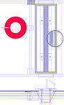
Gun & coil section side view 1:2 - File:Gun coil section side view MetalicaRap vers. 2.0.pdf
Hopper sense ring section side & plan view 1:2 - File:Hopper sense ring MetalicaRap v2.pdf
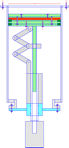
Build platform piston section side view 1:5 - File:Build platform MetalicaRap v2.pdf


For further drawings click here MetalicaRap:Photos and Drawings
Design review
Cost saving approaches
cost saving approaches List;
- Only control via power supply feed back circuit leaving gun cathode to Wehnelt electrode bias fixed via resistor. When at 1KW power and shut down in half a cycle ( 0.2MHz switch frequency) the resonant energy left in LCC circuit and output capacitance would lead to one extra 55micron cube of melted Titanium or 40 microns cube of melted steel. See problem C for calculation Physics Principles/Discussion Yes! big cost savings here!
- filament based around tungsten microscope bulb ( ie flat wound)( sm8018 6V 15W bayonet square filament towards top BA15D ) with top glass dome removed held on remaining glass, half in and out of chamber by 2 viton O rings in bespoke sealing fitting having 2 o rings on inside sealing to bulb glass and on outside 2 more o rings sealing to inside of 2 inch test tube. These o rings are supported by dual grooved on inner & outer aluminum o ring support cylinder which is situated in the 2 inch test tube and which also supports 3 x 304 pillars that attach and support the tungsten Wehnelt cylinder, via 9 in total 1000+ metling point carbon/ceramic/alumina washers, electrical connection must be maintained by tungsten bypass wire or washers being electrically conductive(one; wehnelt hole OD, support rod ID. 2; larger dia. than wehnelt hole OD, support rod ID )[53]The test tube which is half in and out of the chamber is held in its own compression fitting on the end vacuum flange, the test tube is modified with a hole in its end for the bulb filament to protrude out of. A threaded 2 wall cylinder that is clipped in to bulb stub ends on either side of bulb base at one end and pressed against dual grooved inner & outer aluminum o ring support cylinder at the other, and thus provides adjustment of Z position of filament with respect to Wehnelt, accessible from outside of the chamber. A coil surrounds the test tube and a small coil attached to the bulb completes the filament drive "core-less transformer" electrical circuit, when combined with a dimmer circuit connected to coil out side the test tube it replaces conventional filament current control. Thus using a test tube with a home wound coil round it and a modified light bulb provides; -80KV electrical feed-through, -77KV electrical wehnelt feed-through, filament transformer, filament , heat removal mechanism from bulb to test ube, support for wehnelt disc(adjustable height above filament aim 0.3mm) ( also covered with a cap so no pointy HV parts revealed). A user selectable resistor is also included between wehnelt and filament within the test tube. 6.5Keuro saved here.
- Two large TV tubes with screens drilled through with appox 16 inch circular holes enough for build platform, placed face to face with oring between screens, one neck removed where the electron gun is inserted via a o ring, maybe one path to save 2K euro of chamber metal and get 1 set of free electrical feedthroughs for motors (motors working in chamber).
- Since you can get an electron beam to operate in a vacuum of around 5x10^-3 Torr. Avoid metal sealed flanges such as the conflat or wheeler flange By Buna rubber seals and low out gassing glues can be used for sealing components and costly vacuum flanges can be avoided in much of the construction. Simple pipe threads sealed with teflon tape or even glues can be used along with cheaper KF flanges. ( status untested ).
- Avoid expensive vacuum specified water cooled motors operating in the vacuum ( heat dissipation problem) By using oversized normal NEMA motors to cope with overheating and replace any oil filled elements eg gear boxs with a higher temperature white grease. Out-gassing shouldn't be a big problem with grease.;( Status may only last 6 months at a time partially tested) //A hole should also be drilled into the gearbox to allow air to be evacuated.//
- Normally you use use pneumatic vacuum gate valves for the foreline and roughing valves and then a large pneumatic "angle" gate valve for the diffusion pump/ion pump inlet. Lastly, a pneumatic poppet type valve is used to vent the chamber to atmosphere. Avoid the expensive 25.4cm angle gate valve By home-brew using large plumbing valves gate or ball valves for 4 inch and smaller diffusion pumps. See how well home brew valves hold a vacuum BEFORE you put them onto your vacuum chamber. ( status untested).;
- MetalicaRapWin 2nd pump Oil diffusion or ion pumps may be replaced by MetalicaRaps electron beam heating a titanium block within the vacuum chamber, thereby creating a Titanium Sublimation Pump Or what I think we should name it the Electron beam titanium sublimation pump so avoids all gate valves to the second pump since titanium is replenished each atmospheric cycle by the beam melting it and thus also avoids ion pump refreshment /maintenance. ( this new method of pumping relies on a having a very good rough pump vacuum ie 1x10⁻³Torr so the beam can operate to raise titanium to 1300-1600 deg.C. its sublimation temperature. eg Leybold D4 D4B Trivac Rotary Vane Dual Stage 3.4cfm 2K euro new. to 1 x10⁻⁴ torr gas ballast off [54] [55][56] or Kinney KC Series KC-3 pump 2K euro recon. or e.g DS 102 Dual Stage Rotary Vane Vacuum Pump 2 x10⁻³torr 2K euro new. ( these pumps both use oil for lubrication, Oil free called dry pumps are better for EBPVD. (check which PVD metals deposit ok with oil around and which not? ) Dry pump options are currently too expensive eg 10K euro plus; Richards EPX or top end Dry Scroll pumps or Blower Booster paired with own Backing Pump) to protect the chamber put the titanium block in side a double walled box with a beam entry hole at the top, and offset breathing holes through to the rest of the chamber on the box sides, thereby protecting the main chamber from the condensed titanium on inside surfaces of the box and yet let chamber gas combine with titanium creating solid compounds/a chemical pump with inbuilt recovery. Pumping speed may be moderate; for a 13 inch long 1 inch wide by 3 inch high box surrounding the titanium bar , gives a Ti deposit area of 91square inchs, at 20 degC. given pumping speed is 25 litres per second per square inch of deposited Titanium, So Nitrogen pumping speed is 2275 litre per second or 136 m3 / min or 8191 m3 per hour, thus the beam creates its own high vacuum pump. (some tantalum will be advantageous for argon pumping). (Arcing is more likely at poorer vacuum pressures, from the paschen curve we can see that this may not be a problem[57] (should allow / avoid arcing between; cathode to wehnelt 3kV over 0.3mm (same as Pd 3x10⁻²Torr cm at 3KV See graph [58]) - welhnet to anode - 100KV over 34mm (same as Pd 2.9x10⁻⁴Torr cm at 100kV See graph [59])(note; may not work/ may arc at rough pumping pressure levels of 1x10⁻² Torr for argon on wehnelt ( i.e. Pd 3x10⁻¹Torr cm at 3KV See graph [60])))) ( untested but breakthrough if works and probably will especially for MetalicaRapWin with its 10-7Torr vac requiremnt !)
More Examples
Practical manufacturing walk through
Manufacturing walk through Time/Cost
Given Electricity is 2kwh per hour .5Euro/hr Part A Material; Stainless steal, Size; 300x300x200mm Weight; 15Kg 10µ Stainless powder (40 to 100Euro/kg) melt print 100µ Z layer thickness
1 minute per 100µ each layer See below; 1 minute per Z 100µ layer, each layer preheated 20 degrees Centigrade under melting-point followed by printed by beam5.33 minute per Every 10th layer Z axis correction see below ;
SEM ( part assumed to occupy 1/9 of whole print area; 1/9* 300*300=10 000<math>mm^2</math> measurement at every 10µ, SEM picture 500x500 pixel so 5mmx5mm, So for 10,000<math>mm^2</math> need 400 SEM pictures 10,000/25= 400 4x pictures from 4 picups gives effect of different angles? for 3D picture reconstruction so real distances, 400 5mmx5mm pictures, 250ms a picture = 100sec. plus time of mechanical movement of electron gun between .024m square patches at .03m per second is 12y strips each 0.3m strip takes 10 seconds to travel, so in all takes 120 seconds to cover build area( Risk of underestimate factor x100 ) 100+120=220 or 3.66 min flatten blobs through repeated surface spot melting 1ms per 70µ diameter spot area 4000x10-6<math>mm^2</math> ( 850µs duration & 150µs beam movement) 1/10 of part high(Risk of underestimate factor x2) ( 1/10*10 000mm2/ 4000x10-6 <math>mm^2</math>= 1x10⁵ spots 1x10⁵ spots*1ms= 100Sec 1.66min
Time so far 200* Z correction layers 5.33 Min each 1066 + 1800 printed layer 1min each = 2866 min ( 2.0 days) Cost 690 Euro materials 600Euro Electricity 90
MetalicaRap:Further future developments
Critical Design Review, Review of decisions made so far
In chronological order
1.metal.......................... Vs ..composite. ........... .........Why .Metals needed for high stress high temp contexts , engines, solar plants.. -ve ........................ +ve metals 100 % recyclable fits Cradle to Cradle Design See [61]
2.additive.Sintering........ Vs Subtractive EDM?.................Why Tool path manual intervention required.Consumables......... -ve ..Powder management ............ +ve
3.ebeam..Vs laser .....Why A)laser below 50W,small size part 5x5x5cm,slow B) Laser above 150W cost, permit , Wall plug efficiency , optics .-ve .not so cool , difficulty diagnostics...+ve solar cell printer possible
4.powder...........................Vs foil..........................................Why foil waste removal.................................-ve .Harder solid parts.& powder management...... +ve
5.vision & correction sub. Vs one pass blind process ... ....Why .reliability Verifiable tolerance............................................. -ve ...Complexity..................... ................ +ve
6.gravity hopper................ Vs twin chamber........................ Why avoid old powder reuse fresh every time easier prep ............ -ve their must be a good reason to use 2 build chamber? e.g. EOS is. +ve
7.one static top of chamber gun with just sensor ring on cartesian axis Top gun shoots through sensor ring from top........... Vs two gun would ensure spot size on vaporisation but could add in again if existing does not work. Why So SEM near table Sensors PIN Diodes 164$ each not 64x PINdiodes . Pros & Cons of two guns design
8. Water cooling Vs Passive cooling for 5KW gun .............Why .Air cooling fins on cathode head block and on high voltage copper enclosed connector plus ducted fan & fins -ve need to be FEL modeled to check conductance. +ve Simplicity no water ( though could add later ).
9 Tungsten thermionic cathode filament.2600C. Vs .hot Field emission cathode ..Why Cost of IrCe, field emission required UHV, .Thermionic is OK in high vacuum... -ve hot spots poor beam focus reduced filament lifetime, gas load in metal powder more critical due to filament sharing same space.... +ve cheap no need for window to separate gun chamber from powder chamber
10. External coils Vs ..Internal coils in a 304 can..... ....Why .to achieve small enough spot size as spherical aborations are zero on axis of lens and increase as you move out, ... -ve need for barrier between coil pole pieces and beam for vacuum, construction of can for air cooling +ve no contact between coils and vacuum
11. Split hopper ..... Vs ..One large dispenser hopper.....Why ..cost chamber size less force required on motion feed through............... -ve ..complexity of refill mechanism ( shutter with knife edges ) ............... +ve. initial lower cost
...................................... Vs ...............................................Why ...................................................... -ve ..................................................... +ve.......................................
list in importance order, bold text indicates more thought required
Old general infomation
Click for link to Old Information section
Builders Section Very detailed technical information for actual builders only
MetalicaRapBabe elements
Details: MetalicaRapBaby
MetlaicaRapWin Later
Optional beam windows; High tech stationary window or Low tech scanning Aluminum foil slot shaped beam window.
- As the window version will run at 10-7 Torr LaB6 filament is possible (expensive but 1000 hour filament life and 40 times brighter),
- One Self printed Electron beam titanium sublimation pump Or distributed Ion pump with some tantalum, slotted cathode cells for argon gas collection[62] or oil diffusion pump or turbo pump. (prototype uses turbo pump)
- Second pump is a self printed High vacuum Titanium sputter-Ion pump (with some tantalum, slotted cathode cells for argon gas collection [63]) or our invention Electron beam titanium sublimation pump. Prototype before self print, bought in oil diffusion pump (messy with expensive oil 100euro/litre) or turbo vane pump(4K euro extra) .
- Second pump types sputter ion pump or oil diffusion pump will need to be closed off from the chamber during chamber access and roughing pump cycle, to save cost avoiding large gate valves reduced pumping rates will be accepted through the use of smaller radius gate or ball valves with smaller 4 inch or below type pumps . ( later self print gate valves will be investigated)(An oil diffusion pump can not pump at atmospheric pressures and can ruin the oil trying to do so).
- (For ion pump; Use electron guns focus coils to provide magnetic field to sputter ion pump [64] 50L/s max, short duration between maintenance 30Hours , self cathode refreshment by electron beam surface melting exposure in MetalicaRap's beam)
Our high vacuum pump will be a sputter ion pump as has a cost reduction and ease of use advantage for us especially with the window option . As the high vacuum turbo pump cost has been a block to costs coming down, but after redesign an Ion pump seems a good solution, approximately 300 tubes (anodes at 8KV) 15mm diameter 26mm long made of stainless, with 8mm diameter titanium plates ( cathodes at 0V) fitting in either end of anode tubes , leaving a 3.5mm gap for the gas to enter, these are situated around the outside of the lens coils providing magnetic fields in their own stanless steel cans and a 8KV supply hooked up, we have create a electron gun and ion pump combination pump. The number of tubes control the pumping rate it lasts 400 hrs at 1 x <math>10^-</math> <math>^4</math>torr but 40000 hrs at 1 x <math>10^-</math> <math>^6</math>torr . slotted cathode cells for argon gas collection [65]
14 inch pipe (NPS 14 min. SCH 20 ) with one 100mm thick Aluminum plate with interior "carved out" for hopper box sides and top, a further 304 plate for bottom of hopper box with o-ring seal, 304L Top and bottom pipe end caps if not domed min. 18mm thickness typical 25mm thick with copper CF flange and hinged window access.
The refill hopper will be situated in the side of the 14 inch OD diameter gun tube and will obscure a little part of the build chamber from the beam(a necessary compromise). (Technical background: See 5.2 [66]see lecture 4.02/11/04[67],[68]
- Viewing window/ Door 8inch borrsilicate glass, 3/8 thick, standard 10 inch CF plate and Oring.
Detailed Information for builders only General Processes Information
Materials for builders
Intro;Electron Gun B 1-5KW max (63KV ) above build platform. The gun has a small filament chamber followed by a 100.4 mm diameter 304L austentic grain (austentic grain is non magnetic p.243 [69]) stainless steel pipe going through the center of the deflecftion coils but the focus coils for improved efficiency have pole pieces that penetrate the stainless pipe. The coils consist of 2 focus coils and 2 XY interlens deflection assemblies, each XY deflection assembly consisting of 2 pairs of helmholtz coils i air for X & Y deflection respectively.
- Vacuum chamber wall stainless 304 L ; this can be used for walls and pipes and is non magnetic when in Austentic grain state so can be used within magnetic fields. p.243 [70]
- 304L cold rolled (up to 32% reduction ratio 1.04 ok, [ 65% reduction ratio having 1.55 permeability 65% maybe too high permeability for electron poles piece spacers ]), hot forged, electro slag remelt or vacuum remelt or cross forged ,
- 304L pipe cold rolled must be welded without filler,
- To avoid micro cracks (use 304L not 304) and maintain non magnetic properties , Keep 304L at temperature 600 to 750 C for min period during welding ( minuets not hours under 1 hour max or loose non magnetic authentic grain type)
- metals for cathode/1stanode-wehnelt/ anode electrodes '(tungsten /molybdenum/ tungsten,)
- metal for "soft iron core" surrounding coil windings, unalloyed soft iron for yoke use a soft iron, like AISI 1006 [71]; as low carbon as possible. or possible. "Hyperm O", (Cobalt iron alloys for pole pieces if needed e.g. Vanadium Permendur is a superior soft magnet material, but it is VERY difficult to work with and very expensive , and requires fair expertise in heat treating after machining. You should only use it if you need to)
Inter lens X Y deflection coils made from 3 ferite toroid's (N97?), all X deflection coils interconnected, with the first toroid wound in opposite direction from the second and third toroid's and Y deflection coils similarly connected.
- thermal conducting material for anode support structure that extends through high voltage feed through ; Aluminum alloy 6063(Al Mg(0.7)Si(0.4)) connection to 304L via Viton O rings, (could try HelicoFlex [72] or aluminum steel bonding later) to reduce Aluminum out-gassing (ie Al "desorption" worse than 304L steel ) ethanol lubricant during machining is used(as opposed to water based lubricants) (For large Aluminum chambers could also machine in argon atmosphere), p.245 [73]
- glass for cheap but fragile chambers ( and often need outer radiation shielding box ) p 249[74]
- Thermionic emission regime hot filament design; light bulb sm8018 see cost saving approaches below ( copper infused tungsten has also been mentioned as more stable physically)
material for flange ordering:
- 304L stainless steel electro slag remelt or vacuum remelt or cross forged,
- hot forged
- tube ID to be free of hydrocarbon contamination
- white pickled or bright-annealed
- I.D & O.D Clean after manufacturing
- seal in plastic bags
- etched or stamped with part nr, and material type
not allowed:
- sand packing,
- mechanical scratches on tube ID
- any type of lubricant
Avoid the following ;stainless 303 has sulfur in, cadmium and zinc plated screws, brass(permeability 1.55). avoid plastics , avoid O rings contact with solvents. [75]
Materials for lens yokes needs permeability at least a 1000 times greater than pole piece spacers and beam tube. Eg. ASTM 1001 or soft iron[?].
( Prototype ; Vacuum flanges use cross forged 304L stainless ( corss forging breaks up an reorientates leak paths(certainly in flanges over 3 inch to remove micro leak paths that exist in normal 304 plate) (Material sampling As each batch of steal has a unique finger print of number of leak paths/impurities, material sampling can be used to fine the best batch's for High vacuum use.)
Service temperature estimation ; 304 600, Pyrex 400, bulb 250C,, knife edge flange 400C, brass external 150C (not in contact with hot surfaces), fibreboard/glass fibre board 200C (not in contact with hot surfaces), So estimated service temp max is 250C.
Strength vs cost of materials [76] Strength vs Weight [77] Strenght vs Ductility/Brittleness [78] Strength vs Toughness [79] Stiffness vs cost of materials [80] Recycle Fraction vs Cost [81]
Resistance Electrical vs Cost [82] Max service temperature [83]
Window version; For window version UHV LaB6 keep max inclusions to 1 or less for all types see p8 [84]
Vacuum Tech for builders
check for design for; leaks, Virtual leaks , chamber surface area reduction eg minimizing ceramic fish beads insulation, This is a developing detailed process which you improve incrementally in practice.
calculation of process of gas load from;
- seals /volume gas / Calculator here [85] Given a)enclosed volume..m<math>^3</math> b) Volume flow rate capacity m<math>^3</math>/s remove from this o ring leak rates ( for viton 2.5 x<math>10^-</math> <math>^8</math> torr liters / second / linear inch )c) initial pressure mbar d) final pressure mbar Get estimated evacuation time of
- surface gas / permeation/ desorption from materials etc by pump ,
If two pumps backing pump selection calculation.
10-4 torr HV chamber list ; First time chambers conditioning; New O-rings vacuum bake 150o C or several hours next to infa red lamp not over 160o C before installation . If the chamber is a bake-able, metal-gasketed ultrahigh vacuum (UHV) system, baking the system, especially into the roughing pump, would be standard procedure.Avoid cold spots will collect the very contaminants that we need to remove.. Using internal UV 185 /254 nm bulbs to breakup hydrocarbons and infrared bulbs for desorption of water.; If using non capturing type of pump ( eg turbo pump or oil diffusion pump ) where 2 pumps are required, one roughing (i.e. taking the turbo pumps inlet to low enough pressure to be activated, then changing mode to maintaining a appropriate turbo pump inlet pressure for efficient pumping, called roughing pump in backing mode), the inter pump connection line or" foreline " having a diameter above 12cm means you nearly avoid slow pumping molecular flow mode [86] otherwise introducing some Nitrogen in the inter pump line when chamber is below 1 x <math>10^-</math> <math>^3</math>torr will ironically help the roughing pump support the turbo pump better and remove any water .This Nitrogen gas technique is also an extra help for supporting the functioning of the oil sealed mechanical pumps oil traps and light gases in fore line also.
For window version running LaB6 UHV chamber 1 x <math>10^-</math> <math>^6</math>torr ; First time chambers; Flushing the chamber to exhaust with hot nitrogen gas for 1/4 -1/2 hour can be effective in removing surface contaminants (UHV) Could go as far as Glow discharge cleaning[87].
High Voltage for builders
The high voltage bobbin for transformer is an insulating material; HDPE 4mm or cheaper XLPE ( X indicates crosslinked LDPE) or nylon 6/6 insulation, This cross linked low density polyethylene XLPE is used in 11KV to 500KV cables where LPE is set to a fixed form by a process called curing or vulcanization, this can be done via chemical or electron beam radiation. This crosslinking process improves the mechanical stability of the cheaper XLPE products. Comparing the breakdown voltages on different Polyethylene we find that HDPE is 100KV/mm, LLDPE 75KV/mm LDPE 75KV/mm XLPE 50KV/mm p.8[88]]. Other materials include PVC, ceramics, glass, rubber, resins, reinforced plastics, polypropylene, impregnated paper, wood, cotton, mica, pressboards, Bakelite, Perspex, Ebonite, Teflon [89]
Introduction to HIgh Voltage [90]
Shielding Tech for builders
1mm lead shielding is equivalent to :3mm 304 stainless , ??mm sand, ??mm concrete, ??mm standard glass ??mm leaded glass, external box with window cheap ideas?.
Argon gas cylinder needs to be protected from falling over, as long as their is some ventilation the argon gas is no problem, a 60 euro cylinder should provide 3000 chamber purges in window option design ( background info; oxygen 21% of air argon less than 1 %, if oxygen concentration falls below 17% than can effect ill people for healthy people its ok down till 12%, if trace element of CO2 is also present hyperventilation can be triggered which allows no ill effects down to 7% Oxygen. this C02 trace approach is added to argon fire extinguisher systems). For on beam path calculation target penetration based on NIST material testing calculater for 90KV 1.8 mm of lead gives 100% attenuation[91].
Other design options which other builders may choose to follow that we have rejected
Chamber & pumps & feedthroughs
The non window single chamber version can be adapted for Lanthanum hexaboride (LaB6) filaments ( lasting 1000 times longer than tungsten filaments but expensive and needing higher vacuum of 10-6Torr) through creating a dual pressure vacuum chamber design, dividing chamber up between filament/cathode/anode area and the main weld chamber with a mini "airlock" chamber which is high speed pumped. The existing single aperture/ baffle between L1 and L2 magnetic lenses can be cleaved/split in to two separate apertures in two disks thus creating an intermediate mini airlock chamber. The existing aperture size small apertures(100µ) thus doubles up as two air nozzles separating the electron gun from the weld chamber. These 100µ apertures (image size at baffle is 6% of 1mm emitter radius de-magnified by 0.3 so image height is 20µm so aperture will be about 100µ(check)) are suitable size as a pumping aperture/nozzle between electron gun chambers at 10-6 Torr and 10-4 Torr weld chambers. This adaption also requires additional vacuum pumps for each area and the intermediate mini chamber between the baffles.
(Old option: Another option is using 2 recycled TV cathode ray tubes as main vacuum chamber, Leaving only the problem of the build chamber tube which can now self print in 7 pieces and assembled, which is achievable as no longer needs to be vacuum tight only metal powder tight as is within glass Cathode ray tube chambers and cutting the hardened screen glass is successfull. Finally a good way to reuse all those old TV's!) Pumping options ; diaphragm pump no oil Dry
Link to details of High vacuum chamber (initially welded then glued)
- Electrical feed-troughs ; For tungsten filament AC 10A 3V 30W ( NB SM8018 bulb for comparison is 6V 2.5A 15 W flat wound filament but nearly all energy is seen by gun where as only a 40th of ribbon is seen by gun but is 30W 2mm wide 50µ thick ( check)) 50/60Hz heater power supply electrical feed-through includes a oil immersed 100KV isolating transformer using a Pyrex and quartz tubing within CF pipe coupler with orings with oil imersion on outside [92] .By placing last stage of main 100KV power supply the cockcroftwalton ladder in its own vacuum chamber keeps all high voltage ( 100KV) within vacuum(except filament isolating transformer) which allows 15 KV sparkplug type electrical feedthroughs to be used [93] these are welded sparkplugs on CF flanges with out radio noise suppression carbon resistor . A further welded sparkplug type electrical feedthrough will be used for interconnection of 100KV from power supply sub vacuum chamber to main gun chamber. CF flange Electrical connectors, Other (1x 140KV 2KW , , 6x SEM PIN diode pickups low current low voltage,
- Mechanical feed-troughs ; 45Nm torque oring or more leak resistant magnetic feed-throughs 3x 12mm Motor shaft Vacuum chamber motion feed through. 10-5 Torr Low torque version and high torque for 700W build platform motor.
- a dry pump option is better for EBPVD but currently 10K plus euro so rely on back flow oil filtering. ( Aminor issue for metal printing but a problem for solar cell printing is the silicon oil vapor in to the chamber from the oil diffussion pump which will be cracked when in contact with tungsten filament (at 2600 C) producing oil by products that reduce the vacuum and affect the quality of EBPVD [94] melted metal depsoited layers (EBPVD summary by material [95]) .
- Alternative roughing pump is use an oil diffusion pump, there is an existing home build design, see here: [96],[97] (use google translate) though some people have had success with using the chilling unit from an air conditioner in-between pump and chamber [98]. Other electrical feedthrough options includes 100KV sparkplugs with out radio noise suppression carbon resistor [99] with oil immersion on outside. But many commercial machines use the diffusion pumps and cope with the oil issues;The cooled condensation baffles in between the pump and the chamber is adequate to prevent any significant amount of oil getting in the chamber at these pressures. The best way to do wire coils is to seal them into a stainless steel can, and allow a cooling medium like air to ventilate the can. You cannot hope to dissipate much heat from a coil in vacuum, and you don't want the coil to outgas into your vacuum anyway. For the prototype we suggest one gun in a chamber that can be used to test either guns design( Melting gun and vision gun).Once we see the outcome of the test we can decide to try two separate guns again if necessary.
MetalicaRap V2's solution:Buy your 2 sizes of tube cut to length, the larger for gun chamber and build platform chamber the smaller for the spacing rings, glue or weld the smaller pipe rings in the larger pipe, weld in your self printed parts which are now large enough to fit
The chamber surrounding the 12Kg hopper / sensor is too large to print in the build chamber, and you don't want the challenge of welding boxs that are air tight, so you buy a plate as thick as the whole box in Aluminum (cost excludes 304) and slightly over size, remove the build chamber from the bottom of your working printer, clamp the over size plate under it and use your printer in subtractive electron beam machining mode, with the beam striking at an angle by the use of an extra deflection coil, thereby cutting up the material you want to remove and manually breaking the cut bits of with normal hand tools ( other parts are bigger than the build platform like the hopper itself but can be printed in parts and assembled as does not need to be airtight).


Powder Deposition
- The Arcam EMB uses a "textured roller". Presumably a roller is textured with a pattern of holes which is loaded with powder, then the powder falls out of the holes, and a little random redistribution occurs on the way down to the workpiece surface for a reasonably uniform powder layer of repeatable thickness this design will likely operate at ultra high vacuum.
- Leveling the surface of the powder bed or enabling better flow through hopper at ultra high vacuums may be possible using ultrasonic lubrication to briefly fluidize the powder bed. It might cause unacceptable settling though.
- The density of the powder is lower than the density of the solid metal. So if the powder is only deposited using say the textured roller the upper level of the powder bed will get higher than the surface of the part being printed. How is this dealt with in the Arcam printers? More research needed
- Upon beam heating material loss in the form of evaporation and melting is released in to the chamber redepositing itself on windows and light optics and even chemically react with filament ( a minor effect with most materials but a major effect if used in electron beam machining mode where a non metallic backing material or axillary material which is ignited leading to rapid expulsion of auxiliary material that pushes up through the partially mellted hole in the metal work piece above thus causing expulsion of molten metal in the hole, thus creating a cleaner hole shape See 26min in [100]), a slotted disk in combination with a pulsed beam operation and a slotted disk can protect these windows / optics surfaces. (another approach is to use replaceable and disposable glass sheet covers).
Power supply and power control options
- control via power supply feed back circuit leaving gun cathode to Wehnelt bias fixed via gun resistor ( which includes inherent sensing of beam current; as too high beam current means more voltage drop across resistor so more beam pinching so reducing beam current so simple feed back control). When at 1KW power and shut down in half a cycle ( 0.2MHz switch frequency) the resonant energy left in LCC circuit and output capacitance would lead to one extra 55micron cube of melted Titanium or 40 microns cube of melted steel . . See problem C for calculation Physics Principles/Discussion These gun resistor values give 0.94 KW not 0.1 KW look again maybe .For electron optics precision 3KV across Fixed gun resistor (2x 430K Ohm Resistors making Total 215KOhm when arranged in parallel for printing mode (300W rated resistor 50mm x 373mm E12 values [101]), Or 1720 KOhm 4 resistors arranged in series SEM mode, situated in open air air cooling , So beam will run at 940W and 100W respectively 15mA and 1.6mA respectively ) selectable from outside test tube via 3 pole 2 way (6KV) switch solenoid powered by coil on long leads with rectified AC via core less transformer around test tube, ( will need to develop beam calibration current measurement method after filament change possible with 4 pin diode sensing spot size, this approach was found limiting by inability to pulse electron gun due to its parasitic capacitance.
- Use power supply only approach, but with a refinement of 8 fixed value /position adjustable gun resistor so you can put beam current in suitable range to allow for filament change variations, instead of manual rotation ,use fet 4KV & 8x ldr/resistor gate matrix & 8 x led outside test tube. This would make the change of gun resistor automatic. Rejected due to difficulty of finding a FET small enough to go in test tube, ( 200W 4KV up to 30mA)
- Current sensing methods; On transformer secondary (high voltage side) second FPGA on optical link via SFP gigabit modules can sit at -62.5KV and measure current via fixed 40K Ohm (40K non varying element of gun resistor it also has 0 to 140K ohm variable / or via 8 fixed resistors element in 20K ohm steps ) gun resistor their by gaining 30dB Signal noise, ( as opposed to second FPGA siting at 0V sensing beam current across gun resistor via two voltage dividers (-62.5KV to -2V voltage divider), as opposed to using separate (5W 100 ohm) current sensing resistor in earth return from chamber, even less noise but earthing complications with some motor types and requiring some low voltage secondary insulation of chamber) ( power to FPGA via low voltage rectifier and core less transformer via filament test tube ( same method as filament supply but additionally rectified).
- by control of the bias on the Wehnelt voltage in gun ; 0V( full beam wehnelt has same voltage as cathode filament No bias ) to - 3KV pinch off (cut off where wehnelt is at the lowest voltage and cathode filament is 3KV more positive ( i.e. more like anode) ). This bias is achieved via E130L vacuum tube acting as a voltage divider of the main output voltage thereby in effect creating a second voltage supply, OR via 2nd transformer isolated power-supply providing up to 3KV bias. This approach has poor short circuit protection and poor repeatability due to main filament replacement alignment variation).
- by control of the bias on the Wehnelt voltage in gun ; via a second power supply across cathode and Welneht. ( this option is not compatible with the o/p current sense via a ground path resistor as it places a parallel power supply, o/p current sense via a hall device Isolation via a led to photo-transistor 10cm light tube to bring signal to low voltage side/ FPGA side. High voltage side circuit powered by a second core-less transformer across glass test tube used in cathode filament assembly, primary is mains, secondary rectified 5V for LED driver circuit and 15 V for hall current sense device ).
- limit the control option to pulsed operation; use FET series each 800V with transient voltage protection regulator circuit for an x-ray tube with transient voltage protection
- A full high voltage drop across a tetrode ( triode limits bandwidth [102], this tetrode is a safety feature as it controls the current independently of gun but is expensive.
- Push the parallel series converters resonant tank current by 30% so get higher voltage output of 73KV instead of 63 KV. This requires n=19 Cp=18nF Cs=57nF alpha=0.3125 Ls=13.5µH. fo= 181.5Khz. Max duty cycle 0..8. Stress on components increases as Zs Series impedance drops from 333 Ohms to 236 Ohms.
- Voltage multiplier ladder version Cartesian 1kW gun power supply circuit construction will be based around 2 MOT serialized 100KV(1Kw) that gets feeded from a freqency controlled 3 phase switchmode powersupply range 100 Hz to 1 KHz and 8 stage Cockcroft walton ladder for the positive 15 Kv x8= 120KV un regulated, To avoid the need for both; expensive air tight 100KV connecters, and power supply oil immersion , the Cockcroft walton ladder will be situated within the vacuum tank (dead tank with the enclosure at earth potential) in a sub chamber sealed from the main chamber having its own small 8KV ion pump with some tantalum, slotted cathode cells for argon gas collection [103]. The intermediate wall between vacuum tank containing Cockroft walton ladder and main chamber containing gun will be constructed from copper with internal water cooling channels connected to exterior water supply to avoid Diode and resistor overheating problems. With the use of a one way valve between chambers the circuitry remains well insulated unaffected by vacuum loss in the main chamber. .( Cross linking machines already use this vacuum encased powersupply approach).
Cockcroft Walton ladder Calculator Help & Tool for any one who want's a fast overview [104]

- You take heat out of assemblies like this by incorporating water cooling. If you use high purity water (80 meg-ohm) it is reasonably non-conducting electrically, though initially tests will be air cooled vanes on high voltage feed through copper bar.
Deflector coil options
Driver circuit choice Coil position options 1)7 degrees at bottom of gun 2)nearer build table. By rotating the scan raster by 45 degrees in the X Y plane means that we can increase scan speed by product of X and Y coils deflection speeds (in contrast to max X deflection speed equaling max X coil deflection speed), though we do get a lower pointing accuracy.
Practical Tasks for builders
Specific's
- What motor power for build platform vertical motion see scale diagram below ? owned by username ;...........likely finish date :.........emotional status..........
- Which diameter for extension rod inside moterdriven sleeve. I.D. & O.D. sleeve diameters, I.D. & O.D for extention shaft? owned by username ;...........likely finish date :.........emotional status..........
- What motor size & minimum shaft O.D. for hopper X movement/powder deposition ? owned by username ;...........likely finish date :.........emotional status..........
- What is the best Main Deflector Coil driver topology options ; a) Raster 30cmx30cm b) point and shoot owned by username ;...........likely finish date :.........emotional status..........
- What solvent removes conductive coating on outside of salvaged TV tube? Best method to get a clear viewing / illumination window in CRT. Best way to cut hole in screen after pip breakage release of vacuum and capacitive discharge via shorting anode cap to earthing band on four corners of set ( use own cable as anode cable may have diode in[105][106][107]), be safe out there!. owned by username ;...........likely finish date :.........emotional status..........
Broader research (this is the difficult stuff) you need plenty of free time to do these
Your suggested task here (especially pleased if you are going to do it)
- ....................................................................................................................................................................................owned by username ;...........likely finish date :.........emotional status..........
None of the processes in themselves are new, they have all been done in other contexts. What is new is that it may offer finished parts requiring no further machining, verification of parts tolerance and bring error correction to metal powder 3D printing for the first time, thus enabling full-strength finished dimensional parts production.
(add your username, your likely Task completion date , and emotional status comment ;(possibles include " its fun" " its challenging" "wow" "----" "I feel like Robinson Crusoe" " I am so alve" "I am going to be wealthy" .... )
Research Corner Welcomes Your Contribution
If these knowledge areas are new to you, remember to use your networking skills to talk to others, that friend or uncle may be just that expert!
Design/research questions:
- A. Possible pit falls of running an SEM at 100W in four-source photometric stereo Ruderford back scatter mode?
- B. Depth of field of measurements layer errors over 200µ height, typical SEM power is 0.1W?
- C. Target metal surface temperature measurement would be a big advantage, Do you know of a electron bombardment based remote temperature measurement approach?.
- D. Quantify relationship between cathode surface tolerances and electron gun performance, (spot size variation , 2nd order effects etc ) Quantify range of gun performance at cathode tolerances of IT 7.
- E. Which pattern of beam movement a "fixed raster pattern (like a TV scan )" or "point and fire where needed" in a) preheat stage? ( taking temp up to 20 C below melting pointas (commercial printers preheat and infill print method)) b)melting/sintering by following part shape? (scanning coil eddy currents overcome with delays?,scanning blanked out areas leads to time wasting?, variable shaped beam more efficient?, Interference from other signals- X ray , secondary electrons , luminescence , beam induced currents?, Clear path for beam? (commercial printers do edges of parts in this method)
Design question feed back / discussion. Add your ideas here!
MetalicaRap Construction; Physics Principles/Disscussion
See Also
- Metal Delta RepRap v1 - uses a MIG welder to print rough steel forms prior to conventional machining See Open Source Metal PrinterAt Peace research group part of Department of Materials Michigan Tech Past Projects