PWM Driver 1 0
Contents
PWM Driver v1.0
This board is designed to allow you to control high power devices that only have a single polarity. Things like heaters, fans, solenoids, and even motors (you can only turn them in one direction, however.) It takes PWM (pulse width modulation) inputs from a microcontroller such as an Arduino, and converts them into high power outputs. It has 3 channels on each board, and can drive up to 5 amps on each channel with the proper heatsinks.
- You'll need a soldering toolkit to do most of this.
- Read our Electronics Fabrication Guide if you're new.
Buy Components
Refer to the part list generator for information on where to get the stuff you need.
Build Board
Oops! Board Bugs
v1.0
Silkscreen Oops
We forgot a layer on the silkscreen, and the part values are not present. You'll have to refer to the pictures, the PDF in the release files, or the part ID in the BOM to determine what parts go where. Its pretty simple to figure out though. Make sure you get the resistor colors right.
Printed Circuit Board
<div class="thumb tright"></div>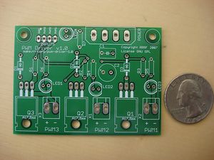
You can either buy this PCB from the RepRap Research Foundation, or you can make your own. The image above shows the professionally manufactured PWM Driver v1.0 PCB ready for soldering. Its also cheap, only $5.00 USD.
File Locations
You can download the electronics files from Sourceforge. This zip file contains the Eagle source files, easy to reference PDF files, the GERBER files used to manufacture the board, as well as a nice 3D rendering of the board. You can even use the PDF files to build it yourself (or the GERBERS to have it manufactured).
Build Process
Soldering
Solder R1-R7
There are two different resistor values, so double check the colors. They can be soldered in any orientation. Polarity doesn't matter. When you are done, clip the long wires sticking out close to the board.
Solder LED1-LED4
These are the LED's to tell you when the power is on, as well as when each channel is active. Simply line up the flat side of the LED with the flat part of the silkscreen and solder away! It is important that you insert them in the proper orientation. They will not work otherwise. When you are done, clip the long wires sticking out close to the board.
Solder D1-D3
These are the diodes to protect the circuit when driving motors and such. There is a stripe on one end of the diode which corresponds to a stripe on the silkscreen. Make sure the diode is oriented in the same direction as on the silkscreen and solder it in. When you are done, clip the long wires sticking out close to the board.
Solder C1
This is the yellowish, circle shaped capacitor. Solder it into the rectangular area for it. The polarity or orientation doesn't matter. When you are done, clip the long wires sticking out close to the board.
Solder C2
This is the cylindrical black and grey capacitor. It has a negative and positive side. The silkscreen has a + sign where the positive side is supposed to go, and the capacitor has a - sign along its negative side. Insert the capacitor accordingly and solder it in. When you are done, clip the long wires sticking out close to the board.
Solder the Power Connector
The power connector is the same one as you find on hard drives in a computer. There are angled parts on the inside of the connector that match up to the markings on the silkscreen. Insert the part according to those, and then solder it in.
Solder X1-X3 (output headers)
These are the output headers that you'll plug whatever device you want to power. Solder the headers with the tabs facing towards the inside of the board. The silkscreen has a top-down representation that should help you if you are confused. Insert the part, and solder it in.
Solder Q1-Q3
These are the power transistors, and they are what turn the signals from your microcontroller into high current to power your devices. Solder them with the flat heatsink tab facing outwards. After you are done, you can either bolt a strip of aluminum to the heatsinks, or you can fold them over to meet the board and bolt them down there. During soldering they may come out of alignment, so it could be sort of tricky.
Solder input wires
Take about 2 feet of the wire from a Cat6 ethernet cable, and take 2 twisted pairs from that. If you want to use the official color scheme, take the blue and brown pairs. Strip about 1/4 inch from the ends of each wire, and solder them into the input holes. You will want to match them up like so:
| Color | Input |
| White/Blue | PWM1 |
| Blue | PWM2 |
| White/Brown | PWM3 |
| Brown | Ground |
When you are finished, twist all the wires into a single cord to keep things tidy.
You have now completed soldering your PWM Driver Board! Do a happy dance and get ready to see if it works.