Sjfw
Release status: working
| Description | Firmware for Atmega644p and greater processors.
|
| License | GNU GPL v3
|
| Author | |
| Contributors | |
| Based-on | [[]]
|
| Categories | Firmware
|
| CAD Models | |
| External Link |
SJFW is a firmware for use with 3d printers. Its unique in that it does not require the Arduino IDE to compile or upload. By breaking away from Arduino's libraries, SJFW proves to be a more efficient, easy-to-use firmware that is very quick. It has been extensively tested on RAMPS and Gen4. Also, SJFW includes binaries (.hex files) in it's distribution. This allows you to skip the compiling step and just put the .hex file onto your printer by any means.
Contents
Features
- Control pad and full HOSTLESS printing!
- "Full' Runtime Configuration!
- Temperature history graph
- Advanced Gcode Pipeline
- ISR driven movement
- Acceleration
- LCD Temperature Display
- "Volumteric" Printing
- SD Card support
- Works well with Pronterface Reprap host
- Supports the following hardware
- Prusa Reprap RAMPS1.2 (experimental!)
- Prusa Reprap RAMPS1.3
- Thing-O-Matic Gen4
Media
These videos are outdated almost as soon as they are uploaded!
Minimums and Requirements
Hardware Minimums
- An Atmel Atmega 1280 or 2560 (644p support coming soon) based 3d printing motherboard
- Your hotend must be either using a 100k thermistor, or a Gen4/3 style extruder controller.
Software Minimums
- ReplicatorG to load the firmware and print
Recommended
- Pronterface host software.
Installing the Firmware
Method 1: Source Code Distribution
This is the "usual" way of configuring and installing a firmware on a Reprap. It's also only for the technically-savvy types, so if you're going to try it, you should already know what to do. In general, we recommend using ReplicatorG to load the generic firmware, under Method 2.
https://github.com/ScribbleJ/sjfw
Method 2: Load the Binaries
If you use the precompiled binaries, YOU MUST CONFIGURE YOUR PRINTER USING GCODE AT BOOT. You can find sample configurations here:
You can either add the configuration to your start.gcode at the /very/ beginning, or you can put it on an sdcard with the name 'sjfwauto.gcd' and it will be run at boot automatically every time your printer starts up. I STRONGLY RECOMMEND THE LATTER METHOD.
Using ReplicatorG
To install the firmware using ReplicatorG, start by downloading and installing the latest version of ReplicatorG for your operating system:
Run it, open the File menu, and choose Preferences. In the "Firmware update URL" put the following: http://scribblej.com/firmware.xml
Close the window to save your changes, then open the "Machine" menu and choose "Upload new firmware."
You should see the following choices:
- Arduino Mega1280 with EC (ToM, Gen4)
- Arduino Mega2560 with EC (ToM, Gen4)
- Arduino Mega1280 with 100k therm (RAMPS13)
- Arduino Mega2560 with 100k therm (RAMPS13)
Choose the one that is appropriate for your machine, and follow the prompts from there. If there is no option appropriate for you, then you must fall back on Method 1.
While RepG is uploading the firmware, it doesn't give any feedback, unless you are looking at the terminal you launched it from. It should take about 1 minute to upload the firmware.
VERY, VERY, VERY IMPORTANT! YOU MUST RUN THE GCODE TO INITIALIZE YOUR PRINTER AFTER EVERY TIME IT IS RESTARTED!
You have TWO good options:
1) The SIMPLE, RELIABLE, and RECOMMENDED WAY: Put the configuration gcode in a file named 'sjfwauto.gcd' on your sdcard and leave it in there every time you boot up.
2) The OTHER WAY: Put the configuration gcode at the very start of your start.gcode file. You may want to keep it around as a file you can run before you try the control panel in your host, too, because you'll need to do that.
Notes
- The Gen4 Support is perfectly useable on a Reprap, but it is designed for use by the Thing O Matic. The important part is this; the Gen4 support ASSUMES you are using the Makerbot Thing-O-Matic EC Firmware on your EC. If you are not, you must install that on your EC first! If you are not using a ToM on Gen4 you will also need to edit the steps settings and speeds/accel in the config file to suit.
Current Issues
- Config file for ramps13 includes everything; the others may need some love for control panel and lcd support.
- Motors that are set to disable after a move only get disabled a few moves thereafter. This should work fine, but don't forget a M84 at the end of your gcode to turn off all motors.
- SD card support works in the firmware, but is not compatible with the Gcodes that Pronterface emits. This firmware presently has two Gcodes for SD access:
M204 - fetch filename from SD M205 - print last fetched filename
- The 4-bit LCD display mode does not always initialize properly from poweron due to timing issues. If your LCD looks garbled, reset the motherboard while leaving the power to the LCD on, sometimes twice in a row. It'll be fine foreverafter, 'till you power down.
- IF your upload of the firmware times out at 99% it almost certainly means you have a buggy bootloader and should replace it with a more recent version. See the Arduino page for details.
- THE SD CODE MAY FAIL ON LONG FILENAMES. 8.3 FILENAMES WORK FINE IN THE MEANTIME.
- There is no homing command. There probably never will be; it's unnecessary. Just make a move towards the endstops that is longer than the platform, then mark that spot with a G92 and carry on. Here's some examples:
Prusa start.gcode
M104 S190 (start heating up, but don't wait)
G92 X0 Y0 Z0 E0 (set current position)
G1 X-300 Y-300 F2000 (Move to X/Y endstops)
G92 X0 Y0 Z0 E0 (set current position)
G1 X5 Y5 (Move away from X/Y endstops)
G92 X0 Y0 Z0 E0 (set current position)
G1 X-10 Y-10 F800 (Move back to X/Y endstops)
G1 Z-200 F400 (Move to Z endstop)
G92 X0 Y0 Z0 E0 (set current position)
G1 Z5 F400 (Move away from Z endstop)
G92 X0 Y0 Z0 E0 (set current position)
G1 Z-10 F400 (Move to Z endstop)
G92 X0 Y0 Z-0.7 E0 (set current position - note endstop is .7 below platform height)
G1 X0 Y0 Z30 F2000 (move to waiting position)
M109 S190 (wait for extruder to reach temperature)
Thing o Matic start.gcode
M104 S180 (start heating extruder, but don't wait)
M140 S50  (start heating platform, but don't wait)
G92 X0 Y0 Z0 E0 (set current position)
G1 Z200 F800 (move to Z endstop)
G1 X-200 Y-200 F2000 (move to X,Y endstops)
G92 X0 Y0 Z0 E0 (set current position)
G1 Z-5 X5 Y5 F800 (move away from XYZ endstops)
G92 X0 Y0 Z0 E0 (set current positions)
G1 Z10 X-10 Y-10 F400 (move to XYZ endstops)
G92 X-5 Y-25 Z116.7 E0 (set current positions)
G1 X0 Y0 Z50 F6000 (move to waiting position)
M84 (disable motors)
M109 S180 (wait for extruder to reach temperature)
Software Setup
There is example gcode in the distribution for use with the precompiled firmware; look in the generic folder to see examples of the Gcode required to configure your printer. The full syntax is documented below, as well.
The precompiled hex files are as generic as possible, but have the SD select pin pre-defined so that you can have the configuration of your particular printer load from SD at boot. If you do not have an SD, no worries, you can still use them, but you'll need to add the configuration code to your start.gcode so it is properly configured before attempting to print.
When using the LCD and Keypad in the generic firmwares, they are hard-coded to expect a 16button pad and 20x4 LCD presently. If you do not have either one, that is fine, but if you do, they must be of that size, or you must compile your own firmware instead of using the precompiled.
Runtime Configuration Gcodes
NOTE: This system of commands is not ideal, but it was quick to implement. It may change later to be more user-friendly and consistent.
sjfw introduces some new gcodes and new usage of gcodes for its own configuration. There is absolutely no intention to have these commands adopted by the community as they are presently.
- M200 - accepts XYZE parameters. Set steps per mm.
- M201 - accepts XYZE parameters. Set start speed in mm/min.
- M202 - accepts XYZE parameters. Set maximum speed in mm/min.
- M203 - accepts XYZE parameters. Set 'average' speed in mm/min. Currently, this can be ignored; it is not used.
NOTE! To avoid any possible issues, always send all four of the commands above together, and always set the steps per mm before the feedrates.
- M204 - no parameters. Returns next filename from SD card.
- M205 - no parameters. Prints last file returned by M204.
- M206 - accepts XYZE parameters. Set acceleration in mm/s/s.
- M207 - accepts P parameter. Set hotend thermistor analog pin, using analog pin number. -1 to disable.
- M208 - accepts P parameter. Set platform thermistor analog pin, using analog pin number. -1 to disable.
"Special" Configuration Gcode
In addition to the above codes, there is a special format for setting pins on all subsystems (except SD card). To begin, you send the code M1 G1 as a single line of gcode, which in other circumstances would be illegal. Then you can add as much pin configuration to the line as you like.
Configuration strings are formatted beginning with a subsystem selector, and from there, configuration options in an arcane format described here:
SUBSYSTEMS:
- '$' - AXIS/Motion Subsystem
- '%' - Temperature Subsystem
- '^' - LCD Subsystem
- '&' - Keypad Subsystem
AXIS Subsystem config
The general format following the '$' specifier is a letter of an axis (note the extruder is 'A' here, NOT 'E') followed by a series of settings for that axis.
The following example contains all the axis-specific commands:
M1 G1 $XSF0DF1ED7IE5A--N0X0
It is possible to break this command down into its parts on separate lines, for readability:
M1 G1 $XSF0 (Set 'X' axis 'S' Step pin to port F, pin 7)
M1 G1 $XDF1 (Set 'X' axis 'D' Dir pin to port F, pin 1)
M1 G1 $XED7 (Set 'X' axis 'E' Enable pin to port D, pin 7)
M1 G1 $XIE5 (Set 'X' axis 'I' mIn endstop pin to port E, pin 5)
M1 G1 $XA-- (Set 'X' axis 'A' mAx endstop to disabled/unused)
M1 G1 $XN0  (Set 'X' axis 'N' iNvert to '0' = false)
M1 G1 $XX0  (Set 'X' axis 'X' disable to '0' = false)
In addition, there are two commands that must include an axis specifier, but take effect globally.
M1 G1 $XJ1K1
- J(1 or 0) Enable/disable Endstop Pullups
- K(1 or 0) Enable/disable Endstop Inversion
PLEASE NOTE, YOU MUST SET THE J/K OPTIONS BEFORE YOU SET ANY AXIS ENDSTOP PINS, OR RE-SET THE ENDSTOP PINS AFTER CHANGING VALUES.
Temperature Subsystem
This subsystem currently only has two options. Here they are by example:
M1 G1 %HB4   (Set 'H'otend FET pin to Port B,4)
M1 G1 %BH5   (Set 'B'ed FET pin to Port H,5)
LCD Subsystem
Here are the options by example:
G1 M1 ^SK1 (Set LCD RS to Port K,7)
G1 M1 ^WL7 (Set LCD RW ...)
G1 M1 ^EK3 (Set LCD Enable)
G1 M1 ^4F5 (Set LCD D4)
G1 M1 ^5K2 (Set LCD D5)
G1 M1 ^6L5 (Set LCD D6)
G1 M1 ^7K4 (Set LCD D7 - always set D7 last, LCD activates automatically when D7 is set.)
Keypad Subsystem
G1 M1 &R0H1 (Set Keypad Row0 to Port H,1)
G1 M1 &R1H0 (Set Keypad Row1)
G1 M1 &R2A1 (Set Keypad Row2)
G1 M1 &R3A3 (Set Keypad Row3)
G1 M1 &C1A7 (Set Keypad Col1)
G1 M1 &C2C6 (Set Keypad Col2)
G1 M1 &C3C4 (Set Keypad Col3)
G1 M1 &C0A5 (Set Keypad Col0 - always set last, is flag for activation)
Subsystem Common Example
If you prefer, you may set multiple commands on one line:
G1 M1 ^SK1WL7EK34F55K26L57K4 &R0H1R1H0R2A1R3A3 &C1A7C2C6C3C4C0A5
Keep in mind sjfw currently presents a 'fragment' maximum size of 32 - the distance between spaces in the gcode line.
Using Special Features
SD Card
PLEASE NOTE: GCode on the sdcard must be 'raw' gcode! No comments in the file, please! PLEASE NOTE: Filenames must be 8.3
- M204 - display next filename.
- M205 - execute the last file displayed by M204.
SD Card Autorun
sjfw includes an option to look for a specially-named file on the sd card and run it at boot. This is especially useful to automatically configure the generic firmwares at boot; just put your configuration gcode in the magic file and it will always run first thing.
The magic filename is 'sjfwauto.gcd'
LCD and Keypad
Currently, the LCD system consists of 3 screens. You can switch between them anytime using the 'A','B','C' buttons on your pad.
Temperature Display/Control
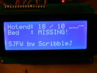
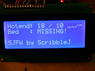 This is the default screen and is selected with 'A'.
The upper right includes a temperature history graph. The center of the graph is always the currently-set temperature.
Keypad controls for this screen:
- 1 = Raise hotend setpoint by 5deg.
- 4 = 0 hotend setpoint
- 7 = Lower hotend setpoint by 5deg.
- 3 = Raise platform setpoint by 5deg.
- 6 = 0 platform setpoint
- 9 = Lower platform setpoint by 5deg.
SD Card Printing
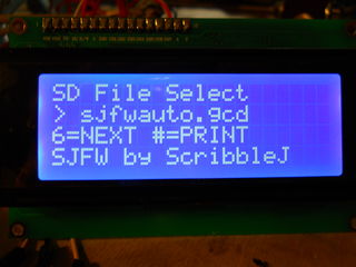 When an SD print is in progress, this screen will change to simply display it's filename.
Keypad controls for this screen:
- '6' = Next file.
- '#' = Print.
Position/Motor Control
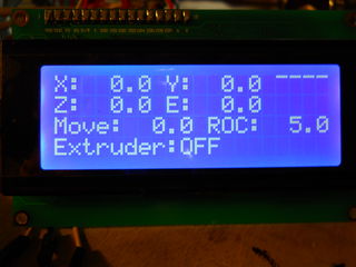 This screen is a bit complicated! Here's what it's showing:
- XYZE = current motor position (at end of parsed gcode, so may not be /current/)
- Upper Right = Temperature history graph.
- Move: When you click an axis move button, it will move this far.
- ROC: When you click the Move Increment/Decrement buttons, the "Move" values changes by this amount.
- Extruder: This /does not monitor the current extruder status/ it simply shows you whether the extruder will run when you move an axis using the pad.
And here are the keypad controls for this screen:
- 1/7 = Move increment/decrement
- '*' = Toggle extruder
- '#' = Next ROC
- '5' = Disable all motors.
- 2/8 = Move Y
- 4/6 = Move X
- 3/9 = Move Z
Customizing Hardware for Additional Features (LCD and Keypad)
There are plans to add i2c support to sjfw as soon as I have an i2c LCD and/or keypad with which to test code. In the meantime, SJFW supports hitachi-protocol text-mode LCDs using a parallel interface. These are as common as dirt; basically any 16x2 or 20x4 character display with 16 pins is going to be the right thing. I recommend 20x4, but the firmware supports both sizes. It /does not/ support single-line displays. If you'd like that support, a patch would be simple.
Keypads are supported using a row/column scanning method. This is a very common style of keypad, and also easy to make yourself. You should expect to see 8 pins for a 4x4 button pad grid. If you have a datasheet, the pins will be labeled COLUMN1-4 and ROW1-4. While it is easy to change SJFW to support 9-button pads or any random number of buttons, currently the code rather assumes you have 16.
THIS MEANS AT A MINIMUM, YOU MUST HAVE (LCD)7 + (KEYPAD)8 = (TOTAL)15 FREE DATA PINS ON YOUR MOTHERBOARD TO USE THE CONTROL PANEL SUPPORT. You can use just the LCD for temperature display without attaching a keypad, if you'd like to save pins. Or you can wait for i2c support.
Below are examples on this for RAMPS 1.3; for other hardware, though this doesn't directly apply, it should help guide you in determining where to put things.
Connecting an LCD to RAMPS 1.3
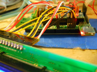
The provided configuration assumes you will connect the LCD in 4-bit mode to AUX2.
- D63 = RS
- D42 = RW
- D65 = E
- D59 = Data4
- D64 = Data5
- D44 = Data6
- D66 = Data7
The Data0 - Data3 pins on the LCD are left disconnected. The contrast pin on the LCD can be wired to ground, or run through a pot between ground and +5v for adjustable contrast.
WHY IS D48 THE UNUSED PIN ABOVE WHEN D65 WOULD MAKE MORE SENSE? Simply because D48 is burned out on my RAMPS board.
WHY CONNECT RW, you know you don't need it, right? Wrong. SJFW uses RW to poll the LCD's busy state for fast, fast, fast access. It is required.
Connecting a keypad to RAMPS 1.3
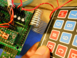
The provided configuration assumes you will connect a 16-button keypad using 8 pins of AUX-4.
- D16 = ROW1
- D17 = ROW2
- D23 = ROW3
- D25 = ROW4
- D27 = COL1
- D29 = COL2
- D31 = COL3
- D33 = COL4
Creating custom config files
If you would like to run SJFW on a configuration that is not currently provided, please contribute your patches after you are done!
SJFW does not use any Arduino-based code, and therefore does not use the Arduino pin numbers, for better or for worse. This means in the configuration files, the pins are specified using Port and pin designations, not Arduino digital pin numbers. If you need some help determining the right values, there are cheatsheets in the util/ directory of the firmware distribution comtaining maps between Arduino pins / Atmega port/pins for Atmega644p and Atmega1280/2560.
You should create a new directory for your config file, and then point the makefile at it.
