Search results
Create the page "Stripboard" on this wiki! See also the search results found.
File:StripboardBipolarStepperController-StepperStripboardUnder 754410.gif Underside of stripboard(342 × 523 (27 KB)) - 08:01, 17 March 2010- ...ication on plain perforated board. The design outlined here uses the same stripboard methods as suggested for other modules and is simpler to build. This image shows the rear of the stripboard so you can see the points that were separated.7 KB (1,092 words) - 05:11, 25 July 2015
File:StripboardJDM-JDMStripboardUnder.gif Underside of stripboard(650 × 385 (48 KB)) - 08:01, 17 March 2010- ...made the circuit for driving the extrusion head conventionally on 2.54 mm stripboard. ...tomatically creating PCBs if you want to etch one, rather than building on stripboard. If you do that, put two 3 mm mounting holes on one edge of the PCB 32 mm52 KB (8,773 words) - 09:49, 5 January 2015
- ...I did not have a [[PWM_Driver_1_1|RepRap PWM PCB]] to hand, and it is that stripboard circuit that is shown.2 KB (344 words) - 14:19, 29 November 2011
- ...Rap controller boards. It is very simple to solder up on an old offcut of stripboard. ...u want to do this, put a 7-pin connector in for P11, make up your circuit (stripboard is probably easiest), and put a 7-way socket on the board that will plug in19 KB (3,040 words) - 04:53, 25 July 2015
- ...u want to do this, put a 7-pin connector in for P11, make up your circuit (stripboard is probably easiest), and put a 7-way socket on the board that will plug in31 KB (5,053 words) - 04:54, 25 July 2015
- ...rt as a drilling jig to drill two 4mm holes near to the bottom edge of the stripboard. Solder the two 4-pin headers near the top and towards either end. Split ...shers down the holes in the driven holder, using the top two to retain the stripboard.15 KB (2,556 words) - 00:59, 5 February 2024
- ...le electronics that can be printed by RepRap itself. Can also be built on stripboard. Fully tested, and supported by the standard RepRap software. ...ew%20Front%20Page/Documentation/Tools/Stripboard%20designer.htm]. See the "Stripboard Designer" section of [[Useful Software Packages]].18 KB (2,604 words) - 08:58, 6 May 2020
- I wired up the control circuit on stripboard, with the power MOSFET on a meaty heatsink. Make sure that all the high-cu13 KB (2,361 words) - 21:26, 8 December 2013
- * [[Pololu Extruder Stripboard]]529 bytes (63 words) - 17:29, 3 February 2011
- |description = Pololu Extruder Stripboard The idea is to make a dead simple stripboard mounted [[Pololu stepper driver board]] and connect it to the existing RepR3 KB (444 words) - 07:34, 10 January 2015
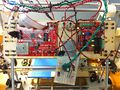
File:Pololu breadboard wiring overview.jpg This will look much nicer once I make a stripboard...(2,592 × 1,936 (2.57 MB)) - 16:42, 26 July 2010- Tony, nice bit of work on the [[Pololu Extruder Stripboard]]! and the [[Filament Spindle]] (pending)!1 KB (169 words) - 14:52, 29 July 2010
- ...holes. The end of the connector should be just flush with the edge of the stripboard.<br clear="all">[[Image:Usb-pcb-connections.jpg]][[Image:Usb-wire.jpg]] ...on the left view. Use a thin cable tie to attach the ribbon cable to the stripboard via the smaller holes. Leave a small loop free to give strain relief. Jum6 KB (891 words) - 14:16, 6 December 2011
- ...the ZD1901 opto interrupter prevalent in the Southern Hemisphere, a simple stripboard assembly is required. Details [[OptoEndstop_2_1#ZD1901_Opto_Switch|here]].15 KB (2,283 words) - 09:52, 14 December 2014
- [[Pololu Extruder Stripboard]],2 KB (326 words) - 06:30, 29 November 2014
- |2.54mm stripboard [[File:Mini-extruder-stripboard-cutting.jpg|400px]]35 KB (6,039 words) - 14:07, 22 November 2015
- <tr><td>'''[[Pololu Extruder Stripboard]]'''</td><td>[[#Experimental|Experimental]]</td><td>''[[#LessThan1YearAgo|< <tr><td>'''[[Pololu Extruder Stripboard]]'''</td><td>[[#Experimental|Experimental]]</td><td>''[[#LessThan1YearAgo|<325 KB (49,064 words) - 06:16, 11 December 2011
- ...hit anything. Try to space the resistors evenly to get even heating. The stripboard goes right under the screw connector (copper away from the aluminium) and p ...(which insulates it from the aluminium), and to attach the screw strip and stripboard.28 KB (4,890 words) - 04:11, 23 September 2013


