Vlad Tepes
Release status: Experimental

| Description | Rigidity Obsessed assembly
|
| License | GPL
|
| Author | |
| Contributors | |
| Based-on | |
| Categories | |
| CAD Models | |
| External Link |
About Vlad Tepes
Vlad Tepes is a historic figure from my country, sitting behind what is known as "Count Dracula". Weird how that happened. The public image about him couldnt be more wrong than that. This short introduction is, ironically, meant to do a little justice to a man who made no compromise about justice.
On short, he lived during very dark times. As time habits were, he was raised at ottoman's court as an "lever" of his father behavior on the throne, e.g. if his father would misbehave then he would of been executed. He came to throne in a context where there was no law, but corruption and criminality were ruling instead. Most of sources blame him for cruelty and executing his enemies, things which arent quite accurate either. He intended to eradicate criminality, so he executed the criminals, at start mostly by sword, like he saw in childhood, but it seemed to be a never-ending job. The choice to impale the criminals instead was meant to leave them there for public awareness, and probably came from the suggestion of one of his aids. The method proved extremely effective and in short time after, criminality was in fact eradicated. He took measures to strengthen the economy and help the working peoples. Among these, he imposed restrictions for traders coming with products from other places (like customs taxes do nowadays). For this he became hated and the outside traders actively plotted to kill him for years. If there is anything that can be said about his rule, is that he made no compromise, in justice or anything else. And who lived long enough knows that making no compromise is not a little thing. Sadly, its what sealed its fate in the end. As a ruler he was loved by the ordinary working peoples which gathered to form army to his aid more than once. His grave is not known - if would be then i suppose i would of researched genetics instead, for a way to clone the guy.
Legend says, one old man made a fountain aside a road for travelers to have fresh water. The recipient used for drinking was supposedly made of gold. One day the man goes to the fountain and the recipient is missing. He then said "Vlad is no longer on his throne".
Little Vlad Tepes knew that a few centuries later, the world would remember him as a guy obsessed with sucking blood out of sexy virgins ... (yummmm to that btw).
This is just one of the many general misconceptions i can see from where i am standing. This also should remind us that general judgments should not be passed about a person, unless we know hard facts, or we actually have been in that person's place for long enough to understand where he comes from. This is obviously not related to reprap, but it is a good example of what kind of misconceptions we can fall prey to. And at which degree it can get to.
If this was *that* far away fetched from reality, then simply who knows what else we have got wrong.
Initial point of view and considerations
- This started as for Vert-X contest, but in the end i feel this is pretty much for myself and not primarily for the contest itself. So, in advance apologies if this doesnt make it in time to meet the deadline.
- Vertical axis setup is considered, with the intent of bringing something extra, in terms of features, versatility etc. In this context having a dual axis for a second toolhead is a direction to explore. Mostly because its so easy to do, e.g. rods will be in a square config, 2 at each side of the Z drive. Having a separate axis could let us have a second toolhead without increasing the weight of the first. There are alot of considrents to it, e.g. there is no current electronics and firmware which could eventually deal with a secondary independent axis. How the second axis could be justified is a question mark, but i am sure it can be put at some use in the end.
- For a number of reasons, i am obsessed with rigidity and the 8mm rods are not inspiring me confidence for the job, so 12mm is the choice, smooth rods + linear bearings. With bigger components and second axis, i think a bigger frame would be in order, at least makes more sense in the context. It probably should use 12mm for frame bars and vertices aswell, but for now will pass on that as it feels kinda much.
- Plastic economy and in general any kind of economic reasons are outside the scope of this.
Initial frame tweaks
1) Rigidity obsession pack: frame "patching" with rod clamps, from place to place, in different positions. For 8mm frame.
2) Accommodation for 12 mm Z smooth rod.
| Angle | Bars dia. | Origins | Comments | File1 | File2 |
|---|---|---|---|---|---|
| 90 deg | 8 + 8 | Mendel | mendel y bar clamp M8 to M8 | y-bar-clamp.stl | openscad file |
| spacer | ~ | Mendel | repurposed to fit the above, as a 5mm spacer between some of the bottom rods | circuit-board-spacer_5mm.stl | openscad file |
| 90 deg | 8 + 12 | Massive Mendel | y bar clamp M8 to M12; two files (~lower and ~upper) | y-bar-clamp ~ | see here |
| Zrod clamp | 12mm Zrod | Mendel repository | old z rod clamp; tweak: to fit M12 Z motor mount; 16mm one for z-motor; 2x20mm ones for underneath clamp. | z-rod-top-clamp ~M12 ~16/20 | openscad file |
| Zrod clamp | 12mm Zrod | Mendel repository | old z rod clamp; as before but for M8 rod | z-rod-top-clamp ~M8 ~16/20 | openscad file |
| 60 deg | 8 + 8 | none | clamp M8 at 60 deg | ? | identical |
| 45 deg | 8 + 8 | none | clamp M8 at 45 deg | ? | identical |
| 30 deg | 8 + 8 | none | clamp M8 at 60 deg | ? | identical |
The above files are grouped here: Tepes_frame_pack.zip
Notes on the initial parts:
- the M8-angle pieces are to add reinforcements from place to place, creatively, i added some wherever i could, and then some more, and then some more again, philosophy being simple: when in doubt, add more M8 threaded bars ... :-)
Design data
Posting some of the design data maybe it will prove of some help. For the nominals i printed sets of geometry pieces in small increments and selected the best fits against real parts i had on hand.
Nominal sizes:
| M size | Type and print direction | Relevant data | Description & Notes |
|---|---|---|---|
| M22 | cylinder horizontal half | r=11.3 | half horizontal cylinder for LME12UU cage |
| M12 | cylinder vertical | r=6.3 | for half of diameter, on z block (zb12~pieces) |
| M12 | cylinder horizontal | r=6.0-6.1 | for half of diameter, on clamp piece |
| M8 | hexagon vertical | r=8 | for nut trap (Prusa similar size = 8.2-8.5) |
| M6 | hexagon vertical | r=6 | for nut trap |
| M5 | cylinder vertical | r=3.0 | M5 thread impaling |
| M5 | cylinder horizontal teardrop | r1=2.75 r2=2 | horizontal teardrop for M5 (lower circle r1, upper circle r2); r1=2.70 makes tight fit |
| M5 | hexagon vertical | r=5.0-5.2 | for nut trap |
| M4 | cylinder vertical | r=2.3 | M4 thread impaling |
| M4 | cylinder horizontal teardrop | r1=2.2 r2=1-1.5 | horizontal teardrop for M4 (lower circle r1, upper circle r2) |
| M4 | hexagon vertical | r=4.3-4.4 | for nut trap |
Notes:
- horizontal cylinders teardrop: main cylinder(r1) + teardrop peak point at half of r1 outside circle, peak flattened by circle arc tangent to both teardrop sides; result is the "classical" teardrop with the peak flattened by the smaller circle(r2) and teardrop sides are tangent to both circles.
- hexagon vertical for nut trap to be made with upper side (bridge area) raised with 0.5-1mm, or to the upper tangent point on circle hexagon; r value is for the outer circle, coincides with hexagon side length.
Small distances for printing - table for quick check and reference purposes:
| Layer height | perim 1.8w/t | loop 1.5w/t | perim+1L | perim+2L | perim+3L | perim+4L | 2perim no loop | 2perim+1L | 2perim+2L | 2perim+3L | 2perim+4L | |
|---|---|---|---|---|---|---|---|---|---|---|---|---|
| 0.40 | 0.72 | 0.60 | 1.32 | 1.92 | 2.52 | 3.12 | 1.44 | 2.04 | 2.64 | 3.24 | 3.84 | |
| 0.30 | 0.54 | 0.45 | 0.99 | 1.44 | 1.89 | 2.34 | 1.08 | 1.53 | 1.98 | 2.43 | 2.88 | |
| 0.28 | 0.50 | 0.42 | 0.92 | 1.34 | 1.76 | 2.18 | 1.01 | 1.43 | 1.85 | 2.27 | 2.69 | |
| 0.25 | 0.45 | 0.38 | 0.83 | 1.20 | 1.58 | 1.95 | 0.90 | 1.28 | 1.65 | 2.03 | 2.40 |
Notes:
- preferred print settings, for rigidity purpose, notably include the following (SF): Fill: extra layers 4+ (each), solid surface layers 6+.
- 2 perimeters e.g. for cases of a vertical hole close to the outside perimeter
- bold values have been considered in some parts
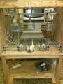
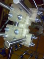
Z axis block assembly
Fixes the rectangle placement configuration of smooth rods. I thought of a chain is as strong as the weakest link. In our case the weakest link is made out of plastic and feels like its this piece in particular (e.g. between x assembly and frame). Also this piece is the cornerstone of a x axis redesign. Impacts on all other parts, motor, belts, carriage, extruder, etc.
Key points:
- meant to fit 4 bars to form 2 independent vertical axis
- could also allow fitting only 2 bars to get a horizontal (classical) axis; even at different heights;
- preferably making it in a single block, (if feels reasonable enough); if not, 2 parts to clamp z drive from either side;
- 4 rods and 2 carriages its alot of extra weight; so this piece needs alot of extra strength compared to old one;
- threaded rod impaled: these get right through the entire part from one side to the other, with nuts on each side;
- distance from the Z rod and Z motor centers - unless fits exactly might be adjustable (for the best);
| Revision | Size | Short comment | Description | STL | VRML2.0 |
|---|---|---|---|---|---|
| 0.0 | 100x70x50mm | z-block | This part is very guilty. Got impaled lots of times M4. Too big, 70mm horizontal. Abandoned. | Media:Zb70x70.stl | wrl |
set 0.1  |
100x50x50mm | z-block | Same as guilty. Actuator thread of z is M6 (not classical M8). Spikes M4. Distance between Zrod and Zmotor axes 30mm & fixed. A way to adjust this would be nice. Part is still pretty big, 50mm horizontal but printable in pla. Added 'mouse ears' in corners for printing. Abandoned. | Media:Zb01zb50.stl | wrl |
| set 0.1 | 41x37.5x16.0mm | lm12 trap | LME12UU trap to fit the above. This one can make the outside trap for version 0.2, because it has a tougher bottom and can resist better when tightening the nuts. | Media:Zb01lm12trap.stl | wrl |
| set 0.1 | 27x40x14mm | rod12 trap | M12 rod trap to fit the above. Abandoned. | Media:Zb01rod12trap.stl | wrl |
set 0.2  |
105x50x34mm | z-block | Had a better advocate - skipped some impaling. Actuator rod of z still M6. LME cage to be accomplished separately. Further slightly shorter version, 34mm height, ~6mm lost in rod clamp space, and rod clamps - M5 threads, bearing clamps - M4 threads still. This revision might be better regarding warping. Added rectangle reinforcements each sides for printing. | Media:Zb02zb34.stl | wrl |
| set 0.2 | 41x37.5x13.2mm | lm12 trap | LME12UU trap to fit the above. From theoretical distance of 13, has +0.2 bottom so all distances fit a par number of 0.4mm layers. Two pcs traps the bearing in the middle. From edge to bearing slot distance to give ~30.2mm between actuator thread and smooth rod centers. No extra on top, the part height finishes right in the middle of M12 smooth rod. This paired with the set 0.1 one (better wall to the nuts side) should fit ok if printer is well calibrated in Z axis. Has to be tried on first with the screws tightened up properly. Only if these are too tight, there is a version with an extra layer. | Media:Zb02lm12trap.stl | wrl |
| set 0.2 | 41x37.5x14.4mm | lm12 trap | LME12UU trap, as above, except +0.4mm higher top side, 1 extra layer, so it overpasses the M12 rod center with that distance. Also the bottom is +0.8mm thicker so it has 2 more bottom layers which would theoretically offset the distance between rod centers accordingly. Added for practical issues, as in case of misfits seems easier to sand the top surface down, than it would be to add something to that face. For example can use one 14.4 and one 13.2 and then there is one extra 0.4 layer in between, or could use both parts 14.4 ones giving two layers. | Media:Zb02lm12trap_14mm.stl | - |
| set 0.2 | 35x34x14mm | rod12 trap | M12 rod trap to fit the above. | Media:Zb02rod12trap.stl | wrl |
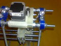
set 0.2  |
56x76x18mm | Z motor | Remake of the z motor mount for 12mm z smooth rod and have the motor position slightly adjustable; rod clamps with the old mendel clamp tweaked at 16mm or 20mm. | Media:Zb02zmadj.stl | wrl |
| set 0.2 | 56x76x18mm | Z motor | Identical part but for normal M8 rod, as alternative for a standard Prusa to have z motor slightly adjustable too. | Zb02zmadjM8.stl | - |
| set 0.2 to-do | ?mm | z nut adj | to-do Reverse Z blocks and use an independent nut trap part to any point on the smooth x rods. | Media:x.stl | wrl |
| set 0.2 to-do | ?mm | z-block M8 | to-do If none of others will do a *dual* vertical x-stage with M8 smooth rods for classic size mendel/prusa. | Media:x.stl | wrl |
| set 0.2 to-do | ?mm | Z-bushing | to-do Maybe add a bushing option as alternative replace for linear Z bearings. | Media:x.stl | wrl |
| set -.- to-do | ?mm | z-block *4 | to-do Might be Zblock cut in half and LME12 bearings trapped in the middle, for printing might be a sandwich of 4 parts. Actuator of z still M6, to be accomplished separately. Might revise horizontal rod distance. Probably most printable setup. Probable disadvantage might be that tightening the rods might result in unwanted over-tightening of the linear bearings, so this variation has to be tested first. | Media:x.stl | wrl |
** VRML - *.wrl : Avoid if unfamiliar. Can get buggy. For Cosmo browser plugin change from defaults in Graphics -> Automatic render change to Direct3D renderer
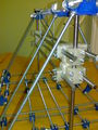
Skeleton structure
Skeleton
X axes
Z block
Zrod


