G3D driver
Release status: working

| Description | New generation stepper motor driver
|
| License | |
| Author | |
| Contributors | |
| Based-on | [[]]
|
| Categories | Electronics
|
| CAD Models | |
| External Link |
This is the new innovative stepper motor driver for your 3D printer or any task involved stepper motors! It is a new generation as replacement for Pololu/StepStick.
Professional design ensure stable operation of this driver - it contain 2oz copper PCB for better heat dissipation and 0.1ohm sense resistors which let it working up to 2A (heatsink and additional air cooling is needed for operating over 1A).
Using standard A4988 drivers you face the problem of vibration / shaking stepper motors and frame when stepper motors are moving (most noticeable on Z stage). These drivers solves this problem by using an additional 30k trimpot to correctly select the off-time settings.
Contents
FAQ
- Is it complicated to use?
- No, you only need to turn the second trimpot (OSC) fully counterclockwise. Enjoy the smoother and quieter stepper motors operation and no more lost steps because of non-optimal or off-time settings.
- For what we need second trimpot ?
- This is just 30k trimpot which turned fully counterclockwise pulling ROSC pin into ground and turning it clockwise let you to choose reference.
- Quoted from A4988 datasheet
- "By pulling the ROSC pin to ground (second trimpot turned fully counter clockwise in our driver), mixed decay is set to be active 100% of the time, for both rising and falling currents, and prevents missed steps. If this is not an issue, it is recommended that automatically-selected mixed decay be used, because it will produce reduced ripple currents. Refer to the Fixed Off-Time section for details."
- You can check A4988 datasheet for more information.
Where to get it?
You can also build it by yourself design files you can find at bottom of page.
VREF Calculation Formula
VREF = I_TripMax * 8 * 0.1
I_TripMax = Peak current through one winding of your motor (A)(other winding will be off)
Note that the current rating shown on your stepper motor is usually for current in both windings.
The peak current through both windings simultaneously will be 70.71% of I_TripMax.
To avoid excessive heating of the stepper motor, particularly if it is bolted to a PLA component, you should set I_tripMax to no more than neccessary to run your printer reliably.
Example: 0.4 A * 8 * 0.1 = 0.32 V
VREF can be measured with a voltmeter between the metal top of the trimpot and GND.
Adjusting the Second Trimpot
This second trimpot is connected to the A4988's ROSC pin. The use of this pin is a bit complex. After careful investigation of the data sheet, this seems to be an appropriate procedure for getting best results:
- Adjust motor current, like described e.g. here.
- Turn the pot fully clockwise.
- Do a slow movement and listen. If you hear uneven microsteps, turn the pot fully counterclockwise. This should make microsteps even. Running at low motor currents makes it more likely uneven steps (some microsteps not taking effect) happen.
- If you didn't have to turn the pot fully counterclockwise and the stepper whines, turn it slowly counterclockwise until the whine disappears (this will raise the whines' pitch, eventually into an unaudible range).
- In case you had to turn the pot fully counterclockwise and the motor whines, the whine is unavoidable.
- Repeat this procedure after each change of the motor current.
Pictures


Design Files
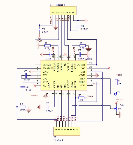
Note: The schematic linked below shows Sense resistors as 0.2 ohm.
The I trip calculation above and the products being shipped use 0.1 ohm sense resistors.
This is a change from the common Pololu design, which uses 0.05 ohm for sense resistors.