Generation 2 OnABoard
This page describes something which is no longer the most recent version. For the replacement version see: "Official" Electronics
Release status: Experimental
| Description | One board to handle most of the gen 2 electronics.
|
| License | unknown
|
| Author | |
| Contributors | |
| Based-on | [[]]
|
| Categories | |
| CAD Models | |
| External Link |
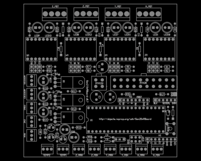
This is a single board that contains most of the electronics required to run a RepRap. All the components that require soldering are through-hole. The cost is slightly less than the generation 2 electronics because there is less need for connectors and PCB space to support connectors.
The board uses the ATMega644P. It can be treated as a Sanguino based Gen 2 electronics and will work with existing firmware that supports the Sanguino.
Contents
Prototype Board fixes
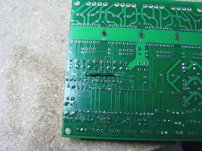
The prototype board (v0.7) has some bugs that need to be corrected to make it function properly.
ICSP Header
The ICSP header has the incorrect pinout. A custom cable is needed in order to fix it and load the bootloader onto the chip. The bootloader only has to be loaded once, so if you have a Sanguino board you can load it with that and then swap the chips.
Reset switch pullup
The pullup resistor on the reset switch is connected to the wrong supply line. It is therefore necessary to run all of the 5v devices off from the 5v standby line instead.
Leave R17 out. Connect the lead on R15 that is nearest to the capacitor to the lead on R17 that is nearest to R15. The connection wire should be insulated so that it doesn't short to the other lead of R15. When this is done correctly, connecting the serial connector while the ATX connector is not connected will cause both LED3 and LED4 to turn on.
ATX connectors
The space between rows is too small. The pins on the connector have to be bent inwards and then pushed through.
PWM base resistors
R11, R12 and R13 need to be replaced by 1 kΩ or less.
PWM diodes
The holes for these D1, D2 and D3 are too small. They have to be drilled out large enough to fit the leads through. A 1 mm drill bit seems to work well. D1 and D2 are connected on the back of the board, so soldering the back side should be fine. D3 should be soldered on both the front and the back of the board in case the via was broken.
The diodes are labeled backwards on the board. The cathode (the side with the stripe) should be farther away from the LEDs than the other side.
To test the diodes after installing them, there should be continuity between the cathodes and 12 V. There should be no continuity between either lead and ground.
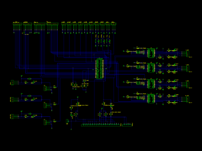
Schematic
Project Files
File:Gen2OnABoard.tar.gz The project archive contains the gEDA and PCB files.
File:Gen2OnABoard.grb.tar.gz This file contains the latest gerber files, which can be sent to a fabricator.
File:Gen2OnABoard.ps This is black and white postscript file containing each layer. It should be useful for fabricating using a toner transfer method.
Circuit Board
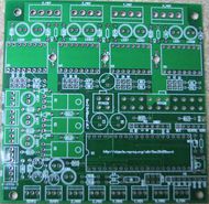
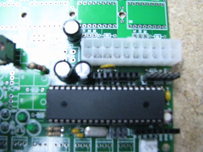
The lower right is an ATMega644P, in a DIP socket. This is the same chip that the Sanguino and the Gen3 motherboard uses. It should be easy to get existing firmware to work with this board.
Near the top I have 4 pololu stepper drivers. See Pololu_Electronics for more information on these boards. Under each stepper driver there are jumpers used to configure the micro-stepping.
On the left side there are three PWM drivers for the fan and two heaters. Each of these can handle 4A continuous, but the total for all three channels can't exceed 8A or the traces that supply them with power might get too hot.
I do not think it will be possible to run a heated bed off from this board. If you wish to try here are my suggestions. Design the heated bed to use no more than 8A (so, at least 1.5 Ohm). When warming up the bed, turn the other two PWM drivers off to limit the total current used by the PWM drivers to 8A. If you exceed 8A, you run a risk of burning the traces on the board. When the bed has reached its working temperature, reduce the PWM duty cycle and then you can use the other PWM drivers as long as you are careful to limit the total average current to 8A. The connectors are only rated to 4A, so you may also want to solder your wires directly to the board. The MOSFET can only handle 4A without a heatsink, so you will have to add a heatsink. If someone tries this, please update this paragraph with your results.
On the right, below the stepper drivers is a 20-pin ATX connector. I'm using the 5V standby to power the microcontroller and I have a pin on the Arduino connected to the power switch wire so that the Arduino will be able to turn the power supply on and off. There is also a 4-pin ATX12V connector to reduce the voltage drop between the power supply and the board.
Between the power connector and the microprocessor there are PTC resettable fuses on each of the 5V and 5V standby lines. These will prevent traces from burning up in the event that something gets connected incorrectly. The 12V and GND lines are not protected in this manor.
The two temp sensors and the AUX sensor have places for a resistor between +5V and the sensor pin. They also have places for a capacitor between GND and the sensor pin. By populating these components it is possible to connect a thermistor directly without using a thermistor board.
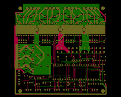
I made all the traces that carry significant current thicker. Most of these are 0.05 inch.
Most of the traces on the top half of the board are on the bottom layer with a ground plane filling the top layer.
Since there isn't much going on under the stepper drivers I filled the bottom layer in that area with a +12V power plane. The idea here is to limit interference between the stepper drivers each pulling from the same supply. Since there can be as much as 10A running through the +12V plane, having a wide path also helps to reduce voltage drop.
I'm estimating this will cost about $125 for the prototype board.
To build a RepRap using this board you will also need a USB-ttl cable, 3 or 6 opto-endstop, a fan to cool the stepper drivers and an ATX power supply.
Suggested Improvements
- modify mask to indicate polarity of LEDs and electrolytic caps - negative cap lead goes in the circular via, positive in the square, LED anode goes in the circular via, cathode in the square.
- modify mask to indicate orientation of stepper driver boards
- correct hole spacing for ATX power connectors
- correct hole diameter for diodes
- increase spacing between crystal and 22pf caps, hole spacing between the leads of each 22pf cap can be narrower. The crystal footprint has to be made bigger. There is little space between the crystal and the ICSP header as well.
- Increase space around the ICSP header. It currently has to be soldered just right to fit the plug on it.
- crystal, 22pf caps, and resistors will fit in the space beneath the massive Atmega 644p IC. This would save a lot of board real estate
- add 5W resistor for power supply load
- fix the GND probe pads
- don't connect 12v to the ATX-20 connector and connect the GND on the ATX-12V connector on the board. This would allow someone to connect a second higher voltage power supply to run the steppers and heaters. Provide a pair of pads somewhere that can be bridged with solder to connect the 12v to the ATX-20 connector in case someone has a power supply without an ATX-12V connector
- Add traces under the footprint of both the pololu stepper boards and the ATMEGA to allow direct use of surface mount chips. 1/2 of the parts cost here is the pololu daughter boards. Mounting those chips directly would save about $8 per, or $32. Adding the traces shouldn't affect the boards usefulness for it's original configuration, nor increase the manufacturing cost.
- Correct the ICSP header pinout.
- Connect the pullup resistor on the reset line to 5V standby instead of 5V so that it operates correctly when the board is only powered by the serial header.
- Run the 5V supply from the serial header through the 5V standby fuse.
- Diodes are backwards on the silk screen.
- Not enough room near the ATX-12V connector for the clip.
- Add i2c headers
- Add a place to solder RS485 chip
Part List
The most detailed part list can be found here:
https://spreadsheets.google.com/ccc?key=0Ajao6Zxy4uHGdEJheVBZOVRqSXJkSlNiVDFaTFNvYUE&hl=en
The best way to order parts is to go to the thingiverse page linked below. At the bottom there is a suppliers link, which will help you develop a shopping list. If suppliers for your region are missing, feel free to add them to the parts. This will help out other users.
http://www.thingiverse.com/thing:2187/partlist
Pin Assignments
| usage | Arduino | ATMega644P | Special Function |
|---|---|---|---|
| X_STEP | D15 | PD7 | PWM |
| X_DIR | D18 | PC2 | TCK |
| X_MIN | D20 | PC4 | TDO |
| X_MAX | D21 | PC5 | TD1 |
| X_ENABLE | GND | ||
| Y_STEP | D23 | PC7 | |
| Y_DIR | D22 | PC6 | |
| Y_MIN | D25 (A6) | PA6 | ADC |
| Y_MAX | D26 (A5) | PA5 | ADC |
| Y_ENABLE | GND | ||
| Z_STEP | D29 (A2) | PA2 | ADC |
| Z_DIR | D30 (A1) | PA1 | ADC |
| Z_MIN | D2 | PB2 | INT2 |
| Z_MAX | D1 | PB1 | INT1 |
| Z_ENABLE | D19 | PC3 | TMS |
| E_STEP | D28 (A3) | PA3 | ADC |
| E_DIR | D16 | PC0 | SCL |
| E_ENABLE | GND | ||
| HEATER1 | D14 | PD6 | PWM |
| TEMP1 | A4 (D27) | PA4 | ADC |
| HEATER2 | D4 | PB4 | PWM |
| TEMP2 | A7 (D24) | PA7 | ADC |
| FAN | D3 | PB3 | PWM |
| PS_ON | D17 | PC1 | SDA |
| ENCODER | D0 | PB0 | INT0 |
| AUX | A0 (D31) | PA0 | ADC |
| MOSI | D5 | PB5 | MOSI |
| MISO | D6 | PB6 | MISO |
| SCK | D7 | PB7 | SCK |
| RX (Serial) | D8 | PD0 | RX0 |
| TX (Serial) | D9 | PD1 | TX0 |
| RS485 IN | D10 | PD2 | RX1 |
| RS485 OUT | D11 | PD3 | TX1 |
| RS485 Tx Enable | D12 | PD4 | PWM |
| RS485 Rx Enable | D13 | PD5 | PWM |
Firmware
5D GCode firmware for Gen2OnABoard (untested)
It was not possible to flash a firmware on my board when the stepper driver boards were plugged in. After removing the driver boards, the firmware flashed on the first try. I suspect they draw a small amount of 5v current, just enough to keep the 644p from flashing.
