RUMBA
|
English • العربية • български • català • čeština • Deutsch • Ελληνικά • español • فارسی • français • hrvatski • magyar • italiano • română • 日本語 • 한국어 • lietuvių • Nederlands • norsk • polski • português • русский • Türkçe • українська • 中文(中国大陆) • 中文(台灣) • עברית • azərbaycanca • |
Release status: Working

| Description | R.eprap U.niversal M.ega B.oard with A.llegro driver
|
| License | |
| Author | |
| Contributors | |
| Based-on | |
| Categories | |
| CAD Models | Altium
|
| External Link |
Contents
Summary
RUMBA (R.eprap U.niversal M.ega B.oard with A.llegro driver) RUMBA is a feature rich all-in-one electronics solution for Reprap and other CNC devices.
It features an onboard ATmega2560. Its six motor outputs are powered by Pololu pin compatible stepper drivers.
The board features a developer friendly expansion port supporting giving access to all unused I/O, ADC and I2C pins.
RUMBA is designed to be flexible in the user's power source availability, allowing any power supply from 12V-35V.
There is also a new variant offered by Makerbase the RUMBA+ .The RUMBA+ offers some newer features.
The most notable being a port for use with touchscreens (TFT) controllers.
There is little support from Makerbase so there needs to be a page adressing setup and use of the RUMBA+.
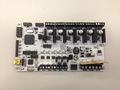
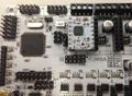
RUMBA board
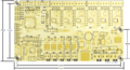
RUMBA PCB hole spacing dimensions
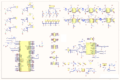
RUMBA schematic
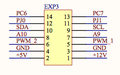
RUMBA schematic EXP3 connector
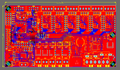
RUMBA PCB all layer


Safety Tip
| |
Caution Once you start putting electricity into your RepRap - even at just 12 volts - you have to take basic, common sense precautions to avoid fires. Just in case these fail, test your workshop smoke detector. Got no smoke detector? Get one! |
RUMBA USB Driver for Windows
| |
NEW : Easy driver setup for Windows 8/7/Vista/XP 32 and 64 bit File:RRD RUMBA TAURINO DriverSetup.zip |
| |
CLASSIC: (can cause problems with Windows 8 and Vista/7 64bit, use the easy method from above instead) When you attach RUMBA for the first time to a Windows computer you might need to provide a driver (INF file). File:RRD-RUMBA USB DRIVER.zip |
Features
- compact size: 135mm x 75mm
- fully integrated all in one solution:
- Arduino 2560-R3 compatible (works with Sprinter, Repetier-Firmware, Marlin out of the box)
- ATmega16U2 (with enhanced firmware) for high speed USB serial connection (up to 2MBit)
- UNIVERSAL POWER:
- can be used with 12V-35V for motors / heated bed
- integrated high precision power regulators (DC/DC) for:
- 12V (FAN/Light/...) and
- 5V (ATmega2560/Logic)
- power input selector for ATmega/logic (stand alone or power from USB)
- easy DISPLAY + SD-CARD connector:
- RepRapDiscount SmartController compatible pin header on board
- up to 6 motor driver with easy micro stepping setup (micro switches) which can be used for:
- TRIPLE extruder
- DUAL Z driver and DUAL extruder
- ...
- 5x temperature ADC connectors for thermistors:
- e.g. 3x extruder thermistor + 1x heated bed thermistor + 1x chamber thermistor
- 5x PWM capable power mosfet outputs (3 with voltage selector for MainPower/12V):
- e.g. 3x (MainPower) extruder heater cartridge/power resistor + 1x (12V) fan + 1x (12V) light
- 1x PWM capable power mosfet with extended cooling area for heated bed
- 6x end stop connectors with power supply
- Xmin/Xmax/Ymin/Ymax/Zmin/Zmax
- can be used for mechanical, opto, hall, ... end stops
- screw terminals *and* pin header for easy motor connection:
- can be used with existing 4 pin Molex plug on motor cable
- easy to attach cables without plug
- USB connector and USB pin header (useful when mounting in a small box)
- Power and ALL unused pins available on EXP-3 feature connector:
- +5V and +12V
- 2x ADC
- 2x PWM I/O
- 4x I/O
- I2C
- full JTAG support
- JTAG can be used during full operation (no shared pins)
- easy to develop/debug new or optimized firmware using Atmel Studio
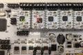
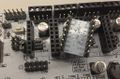
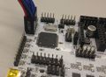
Motor Driver
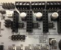
Stepper switches
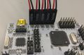
Stepper driver attached
Stepper drivers ok/wrong
Stepper driver back


Microstepping
Some versions of the Rumba contain dip switches located underneath the driver boards, but current versions may contain a row of 3 jumpers.
with DRV8825
| 1 | 2 | 3 | step mode |
|---|---|---|---|
| 0 | 0 | 0 | Full step (2-phase excitation) with 71% current |
| 1 | 0 | 0 | 1/2 step (1-2 phase excitation) |
| 0 | 1 | 0 | 1/4 step (W1-2 phase excitation) |
| 1 | 1 | 0 | 8 microsteps / step |
| 0 | 0 | 1 | 16 microsteps / step |
| 1 | 0 | 1 | 32 microsteps / step |
| 0 | 1 | 1 | 32 microsteps / step |
| 1 | 1 | 1 | 32 microsteps / step |
sources:
from the ic manual. http://www.pololu.com/file/download/drv8825.pdf?file_id=0J590
http://forum.reprapdiscount.com/threads/manual.613/
http://forum.reprapdiscount.com/threads/micro-stepping.614/
with A4988
| 1 | 2 | 3 | step mode |
|---|---|---|---|
| 0 | 0 | 0 | Full step |
| 1 | 0 | 0 | 1/2 step |
| 0 | 1 | 0 | 1/4 step |
| 1 | 1 | 0 | 8 microsteps / step |
| 1 | 1 | 1 | 16 microsteps / step |
Sources:
http://www.pololu.com/product/1182
Motors
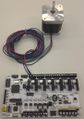
Motor on pin header
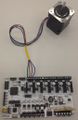
Motor on screw terminal


Note- the commonly used DRV8825 boards (often purple) using the TI DRV8825 chip have a different motor pin out than the A49xx and similar. The silkscreen of A1 B1 B2 A2 matches the A49xx boards. The DRV8825 uses the format of A1 A2 B1 B2, so the coils should be wired together in pairs. This leads to some confusion.
Further, for this user, the nomenclature of 1A 1B 2B 2A was somewhat confusing at first. It is more commonly annotated as I have written it previously (A1 B1 B2 A2) or as A and A-bar (an A with a bar over the top) for A1 and A2 respectively.
Endstops
Endstop cable
Multiple endstop cable


Thermistors
Thermistor cable

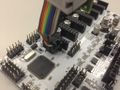
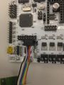
Smart Controller (optional)
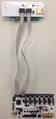
Rumba board and SmartController
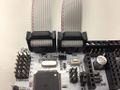
SmartController cable


Run the cables exactly as shown on the images.
The following confusion was encountered with Rumba (board blue LKDR20150602, also see #RepRapDiscount_Smart_Controller) and Smart Controller from kickstarter "Prusa i3 with Diamond Hot end": Rumba-boards small white triangle (pin 1 indication - visible if no plug) is inconsistent with the cable red-line indicating pin-1. And to further "confuse you", the "Smart Controller" plug exp1 must NOT go to exp1 - it should go to exp2 on Rumba. If you orient the plug on Rumba pin1-to-cable-pin1 - and plug exp1-to-exp1 and exp2-to-exp2 you will get the following error meassage when surveying the serial port (via USB on Rumba e.g. with Arduino IDE 1.0.6) (the exact message might differ):
start
echo: External Reset
Marlin1.0.0
echo: Last Updated: Jul 11 2015 13:06:11 | Author: RepRap.me
Compiled: Jul 11 2015
echo: Free Memory: 3632  PlannerBufferBytes: 1232
echo:Hardcoded Default Settings Loaded
echo:Steps per unit:
echo:  M92 X80.00 Y80.00 Z4000.00 E152.00
echo:Maximum feedrates (mm/s):
echo:  M203 X200.00 Y200.00 Z2.00 E25.00
echo:Maximum Acceleration (mm/s2):
echo:  M201 X4000 Y4000 Z50 E1000
echo:Acceleration: S=acceleration, T=retract acceleration
echo:  M204 S3000.00 T3000.00
echo:Advanced variables: S=Min feedrate (mm/s), T=Min travel feedrate (mm/s), B=minimum segment time (ms), X=maximum XY jerk (mm/s),  Z=maximum Z jerk (mm/s),  E=maximum E jerk (mm/s)
echo:  M205 S0.00 T0.00 B20000 X20.00 Z0.40 E5.00
echo:Home offset (mm):
echo:  M206 X0.00 Y0.00 Z0.00
echo:PID settings:
echo:   M301 P22.20 I1.08 D114.00
start
echo: External Reset
...
[Sometimes when termistor T0 is unconnected:]
Error:0
: Extruder switched off. MINTEMP triggered !
Error:Printer stopped due to errors. Fix the error and use M999 to restart. (Temperature is reset. Set it after restarting)
...
and so on...
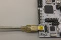
USB
The Rumba uses a standard USB Mini-b (5-pin) female connector.
USB cable

Wiring for the 4-Pin USB Connector:
Starting from the black triangle the pins-outs are:
Gnd data+ data- Vcc
|>______[]________[]________[]________[]
black green white red
RUMBA Wiring
Wiring plan based on available information, may contain wrong information ! / recheck necessary.
A different version of RUMBA has a separate COM port 4-pin block (RX/TX/GND/+5) interior of the 16U2. Need picture and docs.


ATX power supply (controlled with RUMBA)

Set the power jumper in "stand alone" position
Connect GND from your ATX power supply to USB header Pin1 (where the black triangle is)
Connect 5 VSB from your ATX power supply (+5 VDC Standby Voltage) to USB header Pin4
Connect GND and PS ON (Power Supply On) from your ATX power supply to PS ON header, polarity doesn't matter
You'r now able to switch your power supply on and off via gcode or smart controler. With ATX +5 VDC Standby Voltage RUMBA is always powered on even if the power supply is turned of via RUMBA.
FAN0
Can be activated with the usual M106 Sxxx and deactivated with M107 (or M106 S0)
FAN1
Could be activated by using Mcode : M42 P8 Sxxx (0 < xxx < 255)
Marlin Firmware Configuration
Change in Marlin Configuration.h:
#ifndef MOTHERBOARD
  #define MOTHERBOARD BOARD_ULTIMAKER
#endif
to
#ifndef MOTHERBOARD
  #define MOTHERBOARD 80 // Changed BOARD_ULTIMAKER to 80 or BOARD_RUMBA in Marlin v1.0.2. (name BOARD_RUMBA is defined in boards.h)
#endif
if you are connecting the Reprap discount smart controller uncomment this line:
//#define REPRAP_DISCOUNT_SMART_CONTROLLER
to
#define REPRAP_DISCOUNT_SMART_CONTROLLER
If using Mac OS X as host:
#define BAUDRATE 250000
to
#define BAUDRATE 115200 // Changed 250000 to 115200. Arduino IDE 1.0.x on Mac OS X can not use 250000.
To flash your firmware of choice with the Arduino suite you have to select "Arduino Mega 2560 or Mega ADK" as Board.
This following is an example only! Most likely your firmware of choice will have support for RUMBA built in
As of Marlin v1.0.0 pins.h contains the below suggested definitions, you should only need to change Configuration.h as mentioned above.
Add to pins.h:
/****************************************************************************************
* RUMBA pin assignment
*
****************************************************************************************/
#if MOTHERBOARD == 80
#define KNOWN_BOARD 1

#ifndef __AVR_ATmega2560__
 #error Oops!  Make sure you have 'Arduino Mega' selected from the 'Tools -> Boards' menu.
#endif

#define X_STEP_PIN         17
#define X_DIR_PIN          16
#define X_ENABLE_PIN       48
#define X_MIN_PIN          37
#define X_MAX_PIN          36

#define Y_STEP_PIN         54
#define Y_DIR_PIN          47
#define Y_ENABLE_PIN       55
#define Y_MIN_PIN          35
#define Y_MAX_PIN          34

#define Z_STEP_PIN         57
#define Z_DIR_PIN          56
#define Z_ENABLE_PIN       62
#define Z_MIN_PIN          33
#define Z_MAX_PIN          32

//to use Z_DUAL_STEPPER_DRIVER in Marlin
#define Z2_STEP_PIN        26
#define Z2_DIR_PIN         25
#define Z2_ENABLE_PIN      27

#define E0_STEP_PIN        23
#define E0_DIR_PIN         22
#define E0_ENABLE_PIN      24

#define E1_STEP_PIN        26
#define E1_DIR_PIN         25
#define E1_ENABLE_PIN      27

#define E2_STEP_PIN        29
#define E2_DIR_PIN         28
#define E2_ENABLE_PIN      39

#define LED_PIN            13

#define FAN_PIN            7
//additional FAN1 PIN (e.g. useful for electronics fan or light on/off) on PIN 8

#define PS_ON_PIN          45
#define KILL_PIN           46

#define HEATER_0_PIN       2    // EXTRUDER 1
#define HEATER_1_PIN       3    // EXTRUDER 2
#define HEATER_2_PIN       6    // EXTRUDER 3
//optional FAN1 can be used as 4th heater output: #define HEATER_3_PIN       8    // EXTRUDER 4
#define HEATER_BED_PIN     9    // BED

#define TEMP_0_PIN         15   // ANALOG NUMBERING
#define TEMP_1_PIN         14   // ANALOG NUMBERING
#define TEMP_2_PIN         13   // ANALOG NUMBERING
//optional for extruder 4 or chamber: #define TEMP_2_PIN         12   // ANALOG NUMBERING
#define TEMP_BED_PIN       11   // ANALOG NUMBERING

#define SDPOWER            -1
#define SDSS               53
#define SDCARDDETECT       49
#define BEEPER             44
#define LCD_PINS_RS        19
#define LCD_PINS_ENABLE    42
#define LCD_PINS_D4        18
#define LCD_PINS_D5        38
#define LCD_PINS_D6        41
#define LCD_PINS_D7        40
#define BTN_EN1            11
#define BTN_EN2            12
#define BTN_ENC            43
//encoder rotation values
#define BLEN_C 2
#define BLEN_B 1
#define BLEN_A 0
#define encrot0 0
#define encrot1 2
#define encrot2 3
#define encrot3 1

#endif //MOTHERBOARD==80
JTAG & ISP (for firmware developer)
JTAG
ISP ATmega2560
ISP 16U2 (USB to Serial)


ATmega 2560 STK500v2/Arduino2560 Bootloader
HEX: File:RRD-RUMBA ATmega2560 ArduinoBoot.hex.zip
FUSES: E: 0xFD / H: 0x10 / L: 0xFF
- BOD=2.7V
- OCD+JTAG+ISP=ENABLED
- EESAVE=ENABLED
- BOOTSZ=4k
- BOOTRST=ENABLED
- EXTXOSC_8MHZ_XX_16KCK_65MS
Source: Arduino bootloader
16U2 LUFA/Arduino based USB2Serial Firmware
HEX: File:RRD-RUMBA ATmega16U2 USB2Serial.hex.zip
FUSES: E: 0xF6 / H: 0xD9 / L: 0xFF
- BOD=2.7V
- ISP=ENABLED
- EXTXOSC_8MHZ_XX_16KCK_65MS
Source: File:RRD-RUMBA SRC 16U2 FIRMWARE.zip (Atmel Studio 6 project)
Open Source Files
You can find the open source files here: https://web.archive.org/web/20191230213925/http://forum.reprapdiscount.com:80/forums/oss/
An updated version, RUMBA+, has been developed - all source files are available on GitHub.
Where to get it?
- Worldwide: Aus3D (updated RUMBA+ model)
- Worldwide: MakerFarm.com
- Worldwide: opensourcehardware.it
- Worldwide: RepRapDiscount online shop
- France: eMotion Tech
- Germany: reprapteile.de
- Australia: Robotronics
- USA: 3DMakerWorld
- Spain: 3DEspana.com
Troubleshooting
USB connection
This section is "Work In Progress".
Symptoms
Without any reason, the USB connection to the RUMBA is not possible. When connecting the USB cable to the computer, the operating system does not see any device. If the board is provided with a SD card reader, printing with a SD card is still possible.
The RX/TX lights may be stuck on and may/may not flicker when the host is polling the RUMBA over USB. Anecdotal comments point to this happening on a cold startup after a session of successful printing, usually from the day/night before.
Note-- A single user reports that disconnecting the LCD (while trying to upload firmware) solved the problem. This user believes this to be due to the power draw on a "USB Powered" board and the supply limitations of USB of 1A of 500mA (depending on the version, etc). Symptomatically, it was noted that the LCD Screen contrast was diminished, and the measured voltage was 3.8 on the 5V rail, leading to a suspicion of under-volting. In this user's case, entering DFU mode was not possible, likely because the voltages were not reaching the expected High digital level. Before proceeding with the following, try simply disconnecting the higher power devices that are running at this time (motors and the heated bed should be off by default while trying to flash, but other peripherals perhaps...)
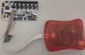
Correction
First, be sure that the problem is not due to a bad position of the power jumper. The problem could be caused by the USB2Serial firmware. Then, you should flash the firmware following these steps:
- Set the power jumper in "USB powered" position.
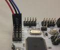
- Place a jumper slightly on the two pins pointed by the white arrow (see picture below). (These are the Ground and Reset pins of the ISP programming header for the ATMega16u4 chip that handles the USB communication.)
- If the board is not mounted on your printer, place it on a clean, dry and insulated surface.
- Connect the USB cable on the board, and connect it on your computer
- Remove the jumper (be careful not to make short-circuit, do not use metallic tools). The TX and RX leds are flashing: the board is now in DFU mode.
Reset pins:

Jumper locations:

If you are running Windows, you can now flash by doing this (Tested on XP, should be fine on higher versions):
- Download and unzip File:RRD-RUMBA ATmega16U2 USB2Serial.hex.zip on your home folder.
- Download and install FLIP from AMTEL.com (Version 3.4.n7 a the time I'm writing this).
- Provide the DFU driver to windows, it should be located in the usb folder of your FLIP installation.
- Once the driver is properly installed, run FLIP.
- Select device ATMega16U2.
- In the HEX file frame, select, if not done yet, FLASH (If done, it should display "Select EEPROM" in the button.).
- Select File -> Load Hex File --> point it to the download hex file (from the first step).
- In "Operations Flow frame", ensure that checkboxes "Erase", "Program" and "Verify" are selected.
- Click RUN.
- You can now disconnect and reconnect the USB cable, and everything should be back to normal.
If you are running Linux or Mac OSX, you can now flash the firmware by doing this:
- Download and unzip File:RRD-RUMBA ATmega16U2 USB2Serial.hex.zip on your home folder.
- Note: Make sure you get the latest version of the Hex file, i.e. . . Arduino-usbserial-atmega16u2-Mega2560-Rev3.hex, the DFU method didn't work on my Mac, I used a Pocket AVR Programmer and the ver3 hex, it worked like a charm.
- Install the software dfu-programmer. You must have the version 0.5.5 or above (Ubuntu 13.10 or higher).
- Mac users can install via Homebrew
$ brew install dfu-programmer
- With root privileges (or sudo command), execute this command line to flash the firmware:
sudo dfu-programmer atmega16u2 flash RRD-RUMBA_ATmega16U2_USB2Serial.hex --force
- You can now disconnect and reconnect the USB cable, and try to connect your host software to the board.
- Another way to verify the fix is to use the "lsusb" command
Install lsusb:
$ brew update && brew tap jlhonora/lsusb && brew install lsusb
Before the fix:
 $ lsusb | grep Atmel
 Bus 253 Device 000: ID 03eb:204b Atmel Corporation Communication Device  Serial: 8533931323335161A100
After the fix (note that it identifies as RUMBA)
 $ lsusb | grep Atmel
 Bus 253 Device 007: ID 03eb:204b Atmel Corporation RUMBA - ATmega 2560 co  Serial: 8533931323335161A100
RepRapDiscount Smart Controller
Symptoms
The smart controller is beeping and flashing, rumba isn't responding.
Correction
On some rumba boards (e.g. board blue LKDR20150602) the silk screen labeling on EXP1 and EXP2 is wrong (- or the Smart Controller silk screen labeling is wrong?) - and turn each connector by 180°.