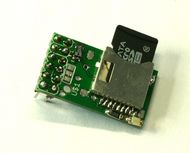
Sdramps
Release status: working
| Description | Run your RAMPS from an SD card!
|
| License | GPL
|
| Author | |
| Contributors | |
| Based-on | [[]]
|
| Categories | |
| CAD Models | |
| External Link |
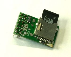
Ever wanted to run your RepRap from an SD card? Here is your chance! This RAMPS add-on enables you to print from microSD. With RAMPS 1.3 and higher it's easily connected to the RAMPS board. You will require special firmware though.
- Kingston brand SD cards do not work as they do not support SPI.
- Kingston brand SD cards do work as long as they are under 2 GB. I have three working on SDRAMPS currently.
Contents
Where to get it?
Depending on the vendor you can buy SD Ramps as bare PCB, DIY-kit or preassembled.
List of suppliers:
- 3dBotShack.com Preassembled and Blank PCBs & Parts
- Austrian Reprap
- Tech3d on eBay
- diy-india.com India
- Charlie's 3D Technologie
- GADGETS3D.com
- ReprapWorld
- LulzBot US
- MixShop.com Canada
- UltiBots assembled
Building your own
Bill of materials
| ID | Name | Type |
|---|---|---|
| PCB | SD RAMPS PCB | PCB |
| C1 | 2.2 µF Tantalum 1206 | Capacitor |
| IC1 | 74HC4050 | Level inverter |
| IC2 | MIC5209-3.3YS | Voltage regulator |
| LED1 | LED1206 red | LED * |
| R1 | 1 kohm 1206 | Resistor * |
| SV1/SV2 | 6x2 stackable header | Header |
| U$1 | MicroSD socket |
NOTE: If you are on a tight budget the LED and Resistor can be omitted and the board will still operate correctly.
Component soldering
The following steps will show you how to solder the board. These components are surface mounted, so this can be a bit tricky. You will need a soldering iron with a small tip. Other than that, it is doable if you have a bit of experience.
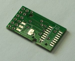
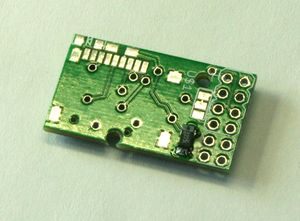
| Step 1 Examine the PCB. Try to figure out what goes where. |
|
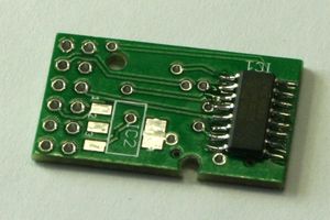
| Step 2 Place the 74HC4050 on the PCB. Some chips do not have clearly marked how they should be put on the board, just place them with text on the chip aligned to the north side of the PCB. Solder one pin (if you are right handed, working from left to right is a good order) and align the other pins to the pad. Solder a second one, check the alignment and then the other pins. |
|
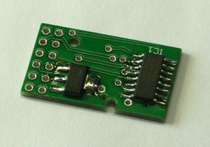
| Step 3 Next is the MIC5209-3.3YS. Place it on the pads and solder the pins. Can't go wrong here. |
|
| Step 4 Turn the PCB and put the capacitor on the pads. Mind the white band! I like to put solder on one pad first, put the capacitor on and melt the solder again. Then solder the other pad. |
|
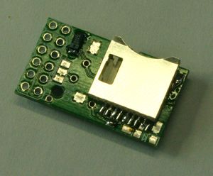
| Step 5 The SD socket is probably the hardest part. Your socket should have eight or nine pins. Place the most left pin on the most left pad. If you have eight pins, a pad on the right remains unused. |
|
| Step 6 Next put the resistor and LED onto the board. The resistor can be put on either way, the LED can only be placed with the +-polarity on the left. |
|
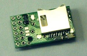
| Step 7 Finally put on the headers and you are good to go! |
Testing your board
For testing your board, I have written a small test program. It will continuously try to detect your SD card. If it succeeds, it will print information about the card. Your should make sure your SD card is formatted correctly.
You can download it here: File:Sdrampstest.zip
Upload the software onto your Arduino MEGA.
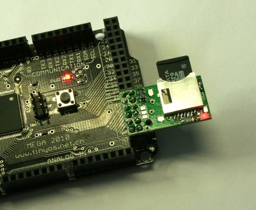
Put your SD RAMPS board onto an Arduino MEGA like this:
The RED LED should light up, indicating the board is powered.
Open the Serial Monitor in you Arduino environment. If the SD card is readable, it should read something like:
Wiring is correct and a card is present.
Card type: SDHC
Volume type is FAT16
Volume size (bytes): 822231040
Volume size (Kbytes): 802960
Volume size (Mbytes): 784
Files found on the card (name, date and size in bytes):
TEST.TXT 2011-08-10 14:14:40 0
TST2.TXT 2011-08-10 14:14:46 0
TST3.TXT 2011-08-10 14:14:54 0
Redesigning and making your own
Through hole shift register AMS1117 (0.8A) as replacement part for MIC5209-3.3YS (0.5A)
Much cheaper availabilty on ie ebay. Easy through hole soldering of shift register (space vs smd component?)
Comments?
Troubleshooting
1. The LED does not light up
Make sure the LED is mounted the right way. If the 74HC4050 is getting hot, you might have a short.
2. The test program says: initialization failed. Things to check: ...
Follow the advise of the program and check every step above. Check if your SD card works.
Using the SD RAMPS
RAMPS 1.3 with Sprinter firmware
These steps will guide you on how to use the SD RAMPS with RAMPS 1.3 and the Sprinter firmware.
Note that you MUST install diode D1 on the RAMPS board if you want to be able to print without being connected to your PC - see: RAMPS 1.4#D1, D2 - Diodes
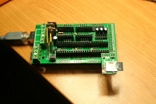
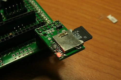
1. Connect your SD RAMPS like this to the RAMPS board:
The four right-most pins are not used.
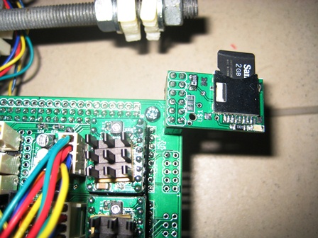
NOTE: On RAMPS 1.4, the corresponding pin pads have been moved a bit closer to the corner of the board, so it looks a little bit different, because the SDRAMPS daughter-board hangs over the corner of the RAMPS 1.4 board a little bit:
2. Download the latest Sprinter firmware from Sprinter
Extract the firmware and open it in your Arduino IDE.
3. Go to the file configuration.h and change the motherboard setting:
- define MOTHERBOARD 33
4. Check that SD card support is enabled:
- define SDSUPPORT 1
5. Make sure you are using 115200 for your baudrate, as Arduino doesn't support 250,000 baud.
6. Compile and upload the firmware.
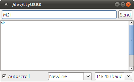
7. Open the Serial Monitor from the Arduino IDE. Make sure the left select list reads newline. Enter the GCode M21 (init SD card). It should return ok.
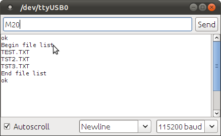
8. Enter the GCode M20 (list files). It should return the contents of the SD card.
9. Further SD commands can be found here: G-code#Unbuffered M and T commands
