File list
This special page shows all uploaded files.
| Date | Name | Thumbnail | Size | Description | Versions |
|---|---|---|---|---|---|
| 23:21, 15 November 2012 | D1D2.jpg (file) |  |
98 KB | 1 | |
| 20:56, 12 March 2011 | PG3 pressedindemo.jpg (file) |  |
61 KB | Shows where to put the wood piece | 1 |
| 17:01, 12 March 2011 | PG3 breakoutassembly.jpg (file) |  |
25 KB | Showing the header pins installed for good measure. | 1 |
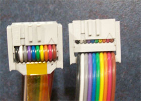
| 17:00, 12 March 2011 | PG3 buildmotherboardcable.jpg (file) |  |
35 KB | Demonstrating how "pin 1" is at the same wire color on both ends | 1 |
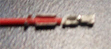
| 16:59, 12 March 2011 | PG3 crimp parts.jpg (file) |  |
471 KB | The collection of parts required to build the endstop plug | 1 |
| 16:58, 12 March 2011 | PG3 endstopconnected.jpg (file) |  |
33 KB | Correct alignment of the endstop header pins | 1 |
| 16:57, 12 March 2011 | PG3 Installstepper.jpg (file) |  |
227 KB | How to correctly align the pins on the stepper drivers | 1 |
| 16:56, 12 March 2011 | PG3 motherboardcable.jpg (file) |  |
46 KB | How to connect the motherboard cable | 1 |
| 16:55, 12 March 2011 | PG3 othercable.jpg (file) |  |
113 KB | Another pre-built cable type | 1 |
| 16:54, 12 March 2011 | PG3 Pin1.jpg (file) |  |
59 KB | Showing the recommended wire selection & position | 1 |
| 16:53, 12 March 2011 | PG3 replacechunkyconnector.jpg (file) |  |
60 KB | Showing what connectors are being discussed | 1 |
| 16:52, 12 March 2011 | PG3 aligned.jpg (file) |  |
22 KB | Aligning the wire in the crimp before pressing it in | 1 |
| 16:51, 12 March 2011 | PG3 almost inserted.jpg (file) |  |
24 KB | Showing how to align pin and housing | 1 |
| 16:51, 12 March 2011 | PG3 inserted.jpg (file) |  |
27 KB | Showing how to assemble the crimp housings | 1 |
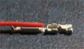
| 16:50, 12 March 2011 | PG3 pressed in.jpg (file) |  |
20 KB | Showing how to crimp pins to wires | 1 |
| 16:49, 12 March 2011 | PG3 pressed in crimp.jpg (file) |  |
23 KB | Showing how to crimp pins to wires | 1 |
| 16:46, 12 March 2011 | PG3 Stress test.jpg (file) |  |
135 KB | Demonstration of crimp strength | 1 |
| 02:52, 12 March 2011 | PG3 001.zip (file) | 533 KB | Fixed the schematic. | 2 | |
| 02:42, 12 March 2011 | PG3 001.pdf (file) | 25 KB | Corrected misrepresentation of how the DIP switch is wired. | 2 | |
| 00:37, 12 March 2011 | PG3 Motor wiring.jpg (file) |  |
64 KB | Wire bipolar motor coils as shown. | 1 |
| 00:33, 12 March 2011 | PG3 Terminal block button.jpg (file) |  |
53 KB | Just pointing out the button that opens the terminal block connectors. | 1 |
| 20:25, 23 January 2011 | PG3 001 footprint.pdf (file) | 23 KB | PG3_001 Stepper Driver Footprint by Dazed.dnc | 1 | |
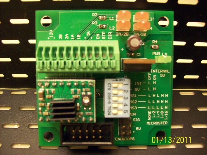
| 20:05, 23 January 2011 | Step driver sm.jpg (file) |  |
151 KB | PG3_001 Stepper Driver by Dazed.dnc | 1 |