LED Stepper Tester v1.0
Contents
Overview
This is a useful diagnostic device that you can use in place of a stepper motor to test your RepRap controller boards. It is very simple to solder up and use.
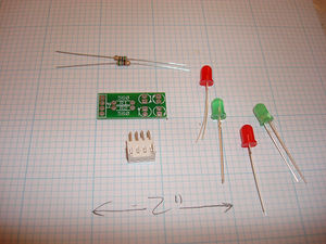
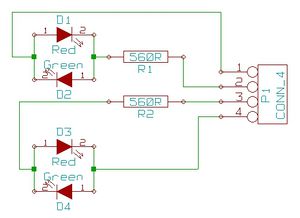
It consists of two green and two red LEDs (though the color scheme is up to you) wired back to back with current limiting resistors. As the L298N (U2) steps the motor the polarity sent to its two coils changes in sequence. If you plug this device in to the stepper connector and use the Step + and Step - buttons on the control window you can see this happening. It works because of the convenient fact that the LEDs don't blow up if you put them in the wrong way round, they just won't glow. Well more correctly they will blow up but need more reverse voltage to breakdown that is available with the other LED clamping the voltage to its forward voltage so the voltage should not rise much over 2V with either polarity drive and most LEDs will not be near reverse breakdown.
- You'll need a soldering toolkit to do most of this.
- Read our Electronics Fabrication Guide if you're new.
- Refer to the bill of materials for information on parts.
Printed Circuit Board
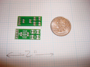
<div class="thumb tright"></div>You can either buy this PCB from the RepRap Research Foundation, or you can make your own. The image above shows the professionally manufactured Power Communications v1.2 PCB ready for soldering. Its also cheap, only $5.00 USD.
File Locations
You can download the electronics files from Sourceforge. This zip file contains the Kicad files, as well as the GERBER files you can use to build it yourself (or have it manufactured).
Build Process
- LED's - polarity important. check silkscreen.
- Resistors - any orientation
- female header connector - put it on the non-silkscreen (bottom) side, and solder on the silkscreen (top) side.
Diagnostic Usage
Stepper Controller
- Both LEDs off: all L298N outputs at ground.
- Red: this output goes + -.
- Green: this output goes - +.
Extruder Controller
You can also use this to test the extruder board. If you plug it into the same 4-pin header on the board, you can see when the board is turning the motor on/off (and which direction) as well as when it turns the fan on and off. You can also plug the first two pins onto the 2pin header for the heater, and it will show you when the heater is turned on (with a lit LED.)


