RAMPSXB
|
English • العربية • български • català • čeština • Deutsch • Ελληνικά • español • فارسی • français • hrvatski • magyar • italiano • română • 日本語 • 한국어 • lietuvių • Nederlands • norsk • polski • português • русский • Türkçe • українська • 中文(中国大陆) • 中文(台灣) • עברית • azərbaycanca • |
This page is a development stub. Please enhance this page by adding information, cad files, nice big images, and well structured data!
Release status: Working
| Description | RAMPS eXpansion Board
|
| License | |
| Author | |
| Contributors | |
| Based-on | |
| Categories | |
| CAD Models | |
| External Link |
Summary
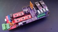
RAMPSXB (RAMPS eXpansion Board) is a shield that attaches to the AUX pins of the common 3D printer control board, RAMPS.
It adds 4 additional stepper motor driver carriers, 4 additional thermistors, 4 additional PWM-controlled MOSFETs, EXP1 and EXP2 for an LCD controller (such as the RepRapDiscount Smart Controller), additional VCC pins, 5V pins, regulated TX/RX for an HC-05 chip, and suppression capacitors on the minimum endstops, similar to the RAMPS 1.4.2.
This allows for a variety of combinations, including 6 completely separate extruders, or a mixing extruder and a few fans, or a mixture of voltages (12V on the main RAMPS, and 24V on the RAMPSXB).
RAMPSXB consumes the maximum endstops, as well as servo pins 2, 3, and 4 to drive the FETs.
Open Source Files
EAGLE files can be found here: https://github.com/SZiv/RAMPSXB
Where to get it?
No manufacturers for this yet. ¯\_(ツ)_/¯ Nothing is too hard to solder, so if you can get ahold of the board, its not very hard to assemble.
Pin Definitions
E2 Direction - 15
E2 Step - 19
E2 Enable - 63
E3 Direction - 2
E3 Step - 39
E3 Enable - 58
E4 Direction - 42
E4 Step - 44
E4 Enable - 49
E5 Direction - 32
E5 Step - 47
E5 Enable - 57
Thermistor T3 - A11
Thermistor T4 - A12
Thermistor T5 - A10
Thermistor T6 - A5
MOSFET H3 - 4
MOSFET H4 - 5
MOSFET H5 - 6
MOSFET H6 - 45
Bill of Materials
| Description | Quantity | Package | Notes |
|---|---|---|---|
| Electrolytic Capacitors, 100uF, SMD | 4 | 0605 | For Stepper Carriers |
| Electrolytic Capacitors, 10uF, SMD | 4 | 0405 | For Thermistors |
| Nonpolarized Capacitor, 0.47uF, SMD | 3 | 0805 | Suppression Caps for Endstops |
| Resistors, SMD, 100k Ohm | 8 | 0805 | For FETS and Pulldowns |
| Resistors, SMD, 10k Ohm | 4 | 0805 | Pullup Resistors |
| Resistors, SMD, 10 Ohm | 4 | 0805 | For FETs |
| Resistors, SMD, 1.8k Ohm | 4 | 0805 | LED current limiting resistors |
| Resistors, SMD, 4.7k Ohm | 4 | 0805 | For Thermistors |
| Resistor, SMD, 3.3k Ohm | 1 | 0805 | Half of a Voltage divider for the HC-05 Chip. No HC-05? You don't need this! |
| Resistor, SMD, 2.2k Ohm | 1 | 0805 | Other Half of a Voltage divider for the HC-05 Chip. No HC-05? You don't need this! |
| MOSFET, Through-hole, stp55nf06l | 4 | TO-220 | Main Power MOSFETs. |
| TO-220 Heatsinks | 4 | TO-220 | Heatsinks for the FETs. Not required, but dirt cheap and suggested. |
| LEDs, SMD | 4 | 0805 | LEDs that tell you if the FETs are on. |
| Screw Terminals | 5 | 3.5mm | Input/output power terminals. If you need more than 4A, solder directly to the bottom traces. |
| PTC Fuses | 1 | N/A | 30V, 9A if you cover the bottom traces for extra power, 6A if you dont. |
| Male/Female Pin Headers | A lot? ¯\_(ツ)_/¯ | 0.1" spacing. | Buy a couple of Female double rows, male double rows, male single rows, and female single rows. |
| PCB | 1 | N/A | The Actual PCB. I get mine from OSHPark, but you can get it from SEEED for better prices. |
