Azteeg X1
Release status: working

| Description | Low cost and Reliable Reprap Electronics
|
| License | CC SA 3.0
|
| Author | |
| Contributors | |
| Based-on | |
| Categories | |
| CAD Models | |
| External Link |
Contents
UPDATES
Version 1.5 is out - Now sports an ATmega1284P micro controller for larger firmware capacity. RoHS Compliant
Introduction
The Azteeg X1 3DP is an open source controller designed to be used in RepRap 3D Printers and similar cartesian based machines including CNCs. It has all the features needed to run all current and future single extruder designs.
The X1 is based on Sanguino/Sanguinololu and is compatible with most Arduino based firmware(Sprinter, Marlin, Repetier, plus others.). It is pin to pin compatible with the Sanguinololu with the addition of a FAN PIN. The X1 features mostly SMT parts to ease production and reduce cost.
Compatible with Pololu and Stepstick stepper motor drivers with the ability to use an external power source for the motors with higher voltages.
The Azteeg X1 3DP is your low cost, compact and expandable 3DP printer controller. Fully Assembled except for the white connectors where you have a choice between right angle and vertical orientation. Soldering iron required.
Features
- Atmel ATmega 1284P (ATmega 644P on v1.0) with FT232RL FTDI USB chip
- Compatible with Sprinter, Marlin, Repetier, others.
- High current capacity connectors and PCB traces.
- Mosfet control for 1 extruder and 1 hotbed
- Extra PWM control for small fan or LEDs
- 3 end stops and 2 thermistor inputs
- 12-30v input high efficiency switching Power supply @ 500ma max
- Dedicated uSD card female header [SDRAMPS compatible]
- Low RDSon Mosfets for less heat buildup
- Input power selector for micro controller [USB or internal regulator]
- Secondary power input for stepper motors.
- Optional pads for TVS spike suppression diodes for the Mosfets
- Mosfet Heatsinks included
- i2C, Tx1 serial, +5, GND, SPI and ADC pins on the expansion ports
- Fast acting blade fuse
- Both right angle and vertical connector sets included
- Lots of LEDs, Rx/TX serial, PWR, hot end and hot bed.
Images
Product Photos
Final version may differ slightly from shown.
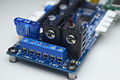
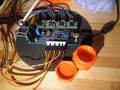
Terminal Block, Fuse and Heatsinks

With Right Angle connectors
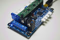
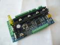
With Pololu Drivers
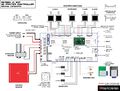
Wiring Diagram


User Photos and videos
mhensen's install
mhensen's install
emmanuel's board, with his own 0.1" screw terminals
Diego's install with custom mount
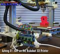
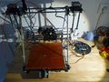
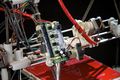
Azteeg X1 runs the BukoBot


<videoflash type="youtube">7gV8H0dhAhI|480|360</videoflash>
Early Prototypes
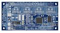
PCB Top Render
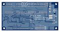
PCB Bottom Render


Files and Documentation
Schematics PDF: http://files.panucatt.com/datasheets/azteeg_x1_schematics.pdf
PCB Source Files(opens with diptrace): http://files.panucatt.com/images/azteeg_x1_diptrace.zip
Wiring Diagram: http://files.panucatt.com/datasheets/azteeg_x1_wiring.pdf
Test code (for Azteeg X1 and Sanguinololu 1.3): http://reprap.org/wiki/File:AzteegX1_Sang_testcode.zip
Getting Started Guide
Hardware
Tools required: Soldering Iron, Solder, Phillips Screw Driver.
1. Solder Connectors - The Kit comes with right angle and vertical connectors so you can choose which configuration is best for your installation. 0.1" pitch terminal blocks can also be used as shown above(Emmanuel's install). Inspect the solder joints after soldering to ensure a good and reliable connection, a loose pin or connector will be difficult to troubleshoot later.

2. Install Heatsinks - Use hardware supplied to fasten the heatsink, Thermal grease is provided but not required for normal operation. Straighten the heatsink before tightening the screws and check that both heatsinks are not touching each other. Use a long nose pliers to secure the heatsink while tightening.

3. Insert jumpers for step size - Consult your stepper drivers documentation to determine your step size settings. See wiring diagram for location and designations of the stepper pins. Push the jumpers all the way down to ensure good contact.

4. Solder TVS Spike suppression diodes[optional][pre-soldered on v1.5] - These diodes help clamp down voltage spikes during on-off switching of the Mosfets. It is not required for normal operation but is highly recommended for stability of the board. The pads(SMB) for these are located at the bottom of the PCB near the Mosfet pins, they can be soldered in any orientation as they are non-polarized, bi-directional versions.
| |
Caution The TVS diodes supplied are rated for 16v, meaning you have to use a power supply lower than 16v(perfect for that 12v power supply of yours). You need to use a higher rated TVS diode(SMB package) if using a higher voltage power supply. |


5. Solder SDRAMPS/uSD Carrier header[optional] - Solder the 2x4 female header on the pads right side of the thermistor connectors(First few units shipped with a female header with pins that are a tad fatter and need a little nudge to put in).
6. Install Stepper Drivers - The Azteeg X1 is compatible with the Pololu style A4983/88, stepstick and other similar drivers. Please see the wiring diagram for pin designations and driver orientation. Incorrect Placement will damage the board and drivers.

7. Wire it up - Use the wiring diagram as a guide to connect power, the heatbed, hotend and the rest of the connectors. Check and double check polarity as you go about. When inserting wire to the terminal block, make sure there are no stray wire strands to create shorts. Crimp the wires and give it a slight pull after inserting into the mating connectors to check that it is locked in(push crimp pins into the housing with a small screw driver if it does not lock in). Use appropriately sized wires, #18-20 for Motors, #22-26 for Endstops and Thermistors. #12-14 for Main supply, #12-14 for Heatbed, #14-16 for the Hotend and keep high current carrying wires as short as possible. Secure all mating connectors all the way into the headers. Tighten terminal block screws.
8. Using secondary power input[optional] - If you need/want to supply your motors with a higher voltage you can use the input connector as shown in the picture. Ensure that your secondary power supply has enough capacity to run the motors. If not using a secondary supply and with the Ext Vmot Jumper installed, the secondary input connector will have 12v(always on) and can be used to power 12v fans or LED strings.
| |
Caution Remove the jumper as shown when installing a secondary power supply, this disconnects the Vmot line from the main supply. Check polarity of power supply wires before connecting, reversing the leads will damage your drivers and most likely the controller. |

9. Last check before power up
- EXT Vmot Jumper is installed (except when using a secondary power supply)
- Input Select Jumper is in INT position(recommended) or in USB(for testing)
- Reset jumper in place(remove only after programming or uploading firmware, having this connected when connecting the USB will reset the controller)
- Stepper Drivers are correctly oriented
- Check all wiring polarity
- Check for loose crimp pins
- Heat sinks are secure and does not touch each other or any conductive part of the board
- All screws of the terminal block are tightened
- Fuse is installed(20amps when using a heated bed and 5Amps when not)
Software
Tools required: - Sanguino Patch for Windows, Sanguino Patch for OSX Arduino IDE ver 0022/0023, Firmware, Mini-USB cable, FTDI USB VCP drivers(optional). Note that, on Mac, copying the "tools" folder as instructed will overwrite the existing folder and all its contents. Copy the nested "avrdude.conf" file to its corresponding path instead.
Bootloader - A bootloader is a piece of code that resides in the controller, it allows you to upload firmware via USB and without using a dedicated programmer like the AVRISP MKII. The Azteeg X1 comes pre-loaded with an Arduino compatible(sanguino) Bootloader for the Atmega644P/1284P chip. To re-burn the bootloader you would need an ICSP programmer like the AVRISP MKII, USBASP, and other compatible devices.
USB Virtual Com port driver - Once you connect your Azteeg X1 to your computer via USB, Windows will detect the USB device and try to install the required drivers. Windows 7 will do a quick update and download the necessary files but in case your OS can't install the drivers, install the FTDI VCP drivers linked above. To verify that the drivers were installed properly, open device manager on windows, click and expand "Ports" and you should see something that says " USB serial port(COMxx)" where COMxx is the com port assigned.
Firmware - Like the Sanguino, Sanguinololu and other controllers based on the ATmega644P/1284P, the X1 needs a patch to run on the Arduino IDE. You can get this Here . The X1 is compatible with most Arduino based firmware and tested with Sprinter, Marlin, Repetier-Firmware. Here's a quick start guide in installing your firmware.
- Let's start off by getting the 0023 Arduino IDE, our Sanguino patch, and firmware Marlin firmwareor Sprinter firmware.
- Install/Extract the Arduino IDE to a folder in your hard drive.
- Once Arduino is installed, copy both "Sanguino" and "Tools" folder from the patch to the Arduino "Hardware" folder. The "Tools" folder contains an update to avrdude's config file to recognize the 1284P processor and will overwrite the existing file.
You Arduino's "Hardware" folder should look like this(it should contain folders named "Arduino" "Sanguino" and "tools").
-->Arduino - Hardware - Arduino Sanguino Tools
Make sure Arduino IDE is not running when perfoming this task.
- Run the Arduino IDE by double clicking on Arduino.exe. Click on Tools --> Board and you should see 2 entries for the Azteeg X1 controller. Select your board version then click on Tools --> Serial Port then select the port assigned for your Azteeg X1. You are now ready to either burn a new bootloader(using a ICSP programmer) or upload firmware via USB. The Azteeg X1 ships with the Arduino bootloader installed.
- Lets use Marlin firmware as an example (you can use Sprinter or Repetier too). With Arduino IDE open, click on file-->open then point to the Marlin folder and look for Marlin.pde then click open. On the Tabs click on Configuration.h and look for the following lines that will initially setup your Azteeg X1. For the Baudrate choose 115200 (250000 will work too) and remember your setting as you will specify this when you connect to your board later. For the Motherboard change the definition to 62 which is the same as the Sanguinololu. At this point you may now change the other settings that matches your setup (e.g. Thermistors, endstops etc.)
define BAUDRATE 115200
define MOTHERBOARD 62
- Setting up the FAN_PIN - The Azteeg X1 is pin compatible with the Sanguinololu except that the X1 has a FAN_PIN that needs to be configured. To do this find the arrow on the right most end of the tabs and click it. Click on pin.h on the drop down selection. With the pin.h window open look for the section that says "Sanguinololu pin assignment" The first line says #if MOTHERBOARD == 62. Scroll down on that section and look for the entry #define FAN_PIN and change from -1 to 4.
define FAN_PIN 4
- Verify your changes - After doing the other changes to match your printer setup. Do a verify to check for error. Click on the circle with a triangle inside on the top left area under "File". If your get some red text on the bottom window that means you have some syntax errors and will highlight the culprit. Once you get the white text saying something like "Binary Sketch size:..." then you're good to upload.
- Upload your changes - If your verify step did not give out an error, you may now upload your firmware by clicking on the box with the arrow inside pointing to the right(upper left corner of Arduino IDE). As the firmware is uploaded you will see the TX/RX LEDs on the board(near the USB port) flashing. No errors? Then your are done with the firmware and can start connecting to your board using your host software like pronterface or Repetier-Host.
Troubleshooting
Issue: Arduino will not compile/load firmware with the following error message.
avrdude: stk500_getsync(): not in sync: resp=0x73
avrdude: stk500_disable(): protocol error, expect=0x14, resp=0x51
Possible Causes: USB VCP driver not installed, incorrect board selection, incorrect serial port selection, faulty USB cable.
Where to get it
At the For Sale forum.