ExtruderImprovementsAndAlternatives
Contents
Extruder improvements and alternatives
Direct drive.
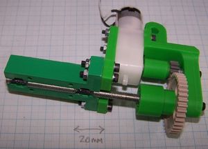
This is a replacement for the flexible drive. It is simpler, and less likely to wear out. Its only disadvantage is that it does not allow the working material a straight run down the extruder - it has to bend. For most working polymers introducing a shallow bend as they enter the extruder is not a problem.
You will need a different motor coupling to the standard one. The design for this is in the motor-coupling.aoi file, called motor-coupling-direct-drive. Export this as an STL and print it.
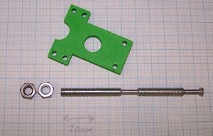
The M6 screw drive is also simpler to make, though it is longer. The reduced diameter bearing lands are in exactly the same arrangement as for the standard extruder, but there is no need to drill an end hole nor to make a separate short section to hold the drive nuts. The drive screw needs to be 96 mm long.
Lock the two M6 nuts on the end against each other very tight. Get some long spanners and turn really hard to get the flats to line up. Don't strip the threads, but don't be frightened of damaging them slightly: they are never going to come undone again.
No-support gear bush holder
The standard gear bush holder needs support material to allow you to build it. But there is an alternative in the gear-bush-holder.aoi file that is in two parts called holder-no-support-1 and holder-no-support-2. As their names imply, they need no support material to build in a RepRap machine, and so should make things much simpler.
They do need two 70mm M3 screws to hold them and the motor together. These will be hard to obtain as actual screws, so just use two 75 mm lengths of M3 studding with nuts and washers on the ends.
There is an extended end with a slot to guide the polymer into the extruder too, which can be useful.
High-temperature heater design
This idea comes from reprapper Ian Adkins of Bits from Bytes.
JB Weld is fine up to about 190 oC. But if you want to go hotter, you need something tougher.
Fire cement fills the bill. It is available from hardware shops and plumbers' suppliers. It is used to fill cracks in chimneys and to seal round flues. The stuff I got goes up to 1250 oC, but don't regard that as a target - you'll degrade the PTFE to some nasty poison gases. The high two-hundreds are a sensible limit.
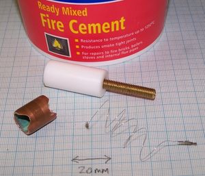
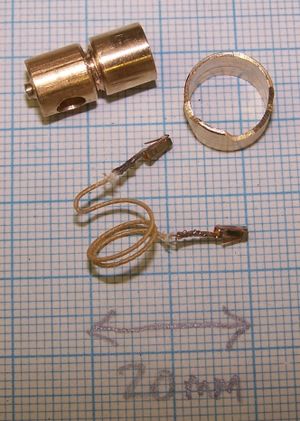
The picture on the right shows the parts you will need: fire cement, the standard PTFE cylinder, the standard brass M6 threaded tube, an 8 ohm length of nichrome heater wire, and an 18 mm length of 15mm diameter copper tube.
You will also need a K-type thermocouple. The extruder heater will get too hot to use thermistors. Thermocouples will be fine, though; unlike thermistors, they also give a linear output with temperature, which makes things simpler.
File two notches in the copper tube at the ends as shown. These will be used to lead the electrical connections through.
The nichrome heater wire doesn't need to be covered in fiberglass insulation, which will make it cheaper and easier to get (maybe from old electric heater?). You definitely can't solder connections to it as it will get too hot and melt the solder. Crimp on two small connectors as in the picture; alternatively use screw connectors.
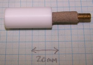
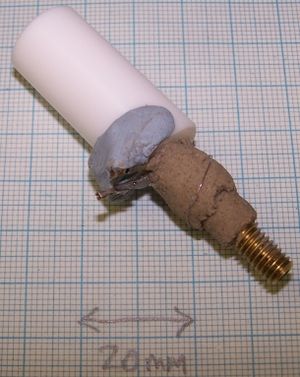
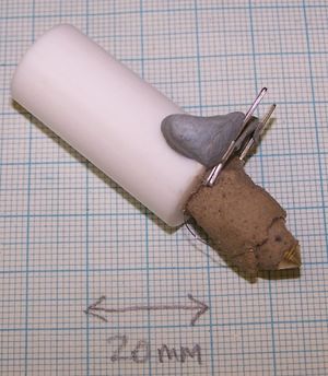
Start by applying a layer of fire cement to the brass tube about 1mm thick and 18 mm long. You will probably find this easier to do with your fingers than with tools. It is also easier to apply too much, then to trim it away with a blade, and then to roll the result between your fingers to smooth it.
Partly set the fire cement with a hair dryer. You don't need to set it completely. Just get it to the point where it is firm and has a dry skin on it.
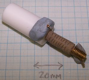
Use Blu-Tack to hold one end of the wire against the PTFE as shown. Wind the rest of the wire evenly over the fire cement, and secure the other end with Blu-Tack.
Check that the wire's resistance is still 8 ohms (that is, check that it is not shorted against itself). Also check that the resistance between it and the brass tube is very high - again, no shorts. (This resistance probably won't be infinite, as damp fire cement conducts slightly. When the fire cement is set dry the resistance will go to infinity.)
Apply a second coat of fire cement. Don't completely cover the wire - you will need to unwind it and lead it back to the top as shown. Again dry the cement with a hair dryer.
Check the resistances again.
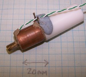
Push the copper tube over and get it roughly central. It may be simpler to have it slightly off-centre to accommodate the connections. This doesn't matter.
Push the thermocouple into the cement at the bottom.
Completely fill all gaps with fire cement. Push it in and tamp it down with a small screwdriver, but take care not to disturb the wire coil.
Again check the resistances, this time also making sure that the copper tube is isolated too, and that so is the thermocouple.
Clean the thread by running an M6 nut down the brass.
Attach the thermocouple to the RepRap thermocouple circuit and attach that to an Arduino as described on that page. Load the thermocouple program at the foot of that page into the Arduino and run it. The temperature should read room-temperature.
Attach a variable-voltage power supply to the heater coil and place the extruder heater vertically. It's going to get hot, so if (unlike me) you value your bench you may care to stand it on a small block of wood.
Turn on the power supply. Start with about 3v and check that the temperature rises slowly.
Over the space of a few hours come back and increase the voltage by about 0.5 v every so often. The idea is to ramp the temperature up very slowly to dry everything out without subjecting it to thermal stress. Stop when you get to about 250 oC.
Very simple nozzle...
...but nonetheless very effective, particularly at extruding ABS. This is because it has a very uniform temperature and can easily run hot; the lack of a separate nozzle reduces cooling at the tip.
Here are the parts. The PTFE rod is exactly the same as the one on the standard extruder.
The nozzle is all in one piece: a length of M6 brass studding with a conical tip. Cut a 48 mm length of M6 brass studding and face off the ends in a lathe. Drill a 44 mm deep 3.5 mm hole down it using a woodpecker cycle to remove swarf.
Then turn the studding round in the chuck and clamp it so it just projects slightly. Put a very small centre drill in the tailstock, again just projecting slightly (you want both dead centre, and so are trying to minimise offsets caused by the studding and the centre drill being out of true). Just touch the centre drill on the flat face to make a very small dent. Then put an 0.5 mm drill in the tailstock and very carefully drill through from the centre you have made to the 3.5 mm hole coming in the other direction. My tailstock chuck is too big to hold an 0.5 mm drill, so I put the drill in a pin chuck, then put that in the tailstock.
Finally turn the toolpost to 45o and turn the cone. Don't be frightened to cut away a little of the 0.5mm hole you drilled previously. When you've finished you'll probably have to clean up the 0.5mm hole with the drill you used to make it, together, perhaps, with a little fine emery paper.
I made the nichrome heater wire 7 ohms. Crimpable bootlace ferrules (RS ones are here) make attaching the heater to the connection pins easy. Wrap a little nichrome round the pin a few times, put the ferrule over it, and crush it hard.
To get the length of the 15 mm copper plumbing pipe, screw the M6 studding into the PTFE firmly, then measure off against it. You want the copper to be the length of the exposed studding to the start of the cone plus about 10mm. Cut the pipe, then hacksaw 10mm away from one end leaving a tab as shown. Bend the tab back at right-angles to the pipe.
Use fire cement as above. The instructions from here on are identical.
Make sure you leave enough room just behind the tip to fit a temperature sensor (either a high-temperature thermistor or a thermocouple). I used a K-type thermocouple.
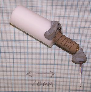
The finished nozzle.
Get your temperature sensor as close to the barrel as you can without touching it, and get it as near the nozzle as possible while still retaining it strongly in the fire cement. For a thermocouple I wrap a square centimeter of PTFE plumber's tape round the welded end of the thermocouple before pushing it into the fire cement to electrically insulate it. This forms a film that is so thin that it will not inhibit the flow of heat. Thermistors are in an insulated covering (usually a glass bead) anyway.
As you can see, I use a twist of fine wire to retain the thermocouple wire on the PTFE barrel. I hapen to have some PTFE-covered wire, which is good against heat, of course. If you have plenty of thermocouple wire, you could use a twist of that - its PTFE insulation will better withstand the heat than that for ordinary wire.
The tab is to stop the screw coming undone with the pressure of the molten polymer in the heater barrel (the friction between the PTFE and the brass thread is very low).
After the fire cement has been heated and has set bend the tab back against the surface of the PTFE. Using a small electric hand drill, drill a 1.5mm diameter hole through the PTFE along a chord (i.e. not along a diameter) so that it misses the brass screw. Drill the hole on the side of the tab towards which it would move if the brass screw were to unscrew. Then screw in a short M2 screw to retain the tab. There is no need to tap a thread in the PTFE first - it is soft enough that the screw will cut its own thread.
Nozzle valve
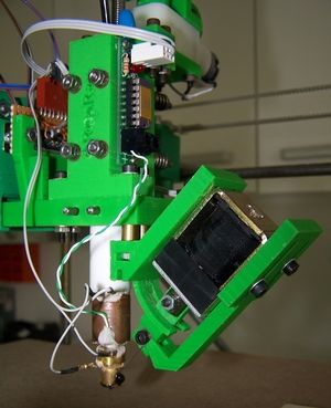
This device allows the flow of polymer to be controlled with much more precision than simply turning on and off the extruder motor. It consists of a latching solenoid that pushes a piece of stiff piano wire across the exit to the nozzle, blocking it. This doesn't completely stop the flow, but it does eliminate a lot of leakage. It also allows tricks like starting up the extrude drive motor with the valve closed, building up a little pressure, then opening the valve to ensure a clean sharp start to polymer deposition. Controls for all that sort of thing are available in the RepRap Java software and in the Arduino (and PIC) controllers.
The design is not perfect - it does slowly leak a little polymer at the side, as you can see from the picture.
The solenoid I used was from RS, catalogue number 250-0827. This is held by the green RP parts shown. The designs for them are in the RepRap Subversion Repository here. The assembly attaches under the extruder using two of the four bolts that hold the extruder together, again as shown. You may need to add spacers to get the alignment right (the stacks of brass M3 washers you can see in the picture). The line of action of the solenoid needs to align with the movement of the piano wire in the valve, described below.
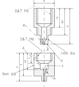
Here is a drawing of the two brass parts of the valve. This is in the repository here.
The nozzle is an 0.5mm vertical hole exiting from the bottom of the bottom half of the device. An 0.5mm diameter length of piano wire slides in an 0.5mm hole at 45o to that along the axes marked A-A, which coincide when the device is assembled. The big problem that this design overcomes, and the reason that it is a little complicated, is that of getting those two holes to cross exactly in alignment in the middle of the device. It's quite easy to get them to cross at the exit (one just drills the 45o hole using the nozzle flow hole as a centre), but that leaks - the crossing point has to be in the middle.
Making these parts has to be done in the right sequence. Start with the top one. The only tricky part here is drilling the 45o hole, and that is done as just described: drill the vertical 0.5mm hole first, then clamp the nozzle in a drill's vice with that hole pointing at 45o upwards, then drill the 45o hole using the original hole to centre the drill.
Next make the bottom part. Drill and tap all the large vertical holes, and turn down the nozzle, but don't make the 3mm horizontal hole nor the 45o hole, nor the 0.5 mm nozzle hole yet.
To make the flat-bottomed hole you will need a 4mm slot drill (conventional drills have a cone at the end, of course).
The important thing is to get the device so that, when you screw the two halves together, the two faces marked F-F are pushed hard against each other. You can check this by putting a little engineer's blue on the top face. Screwing the device together should transfer some of this by friction to the flat-bottomed hole.
On the top half, mark the side of the 8mm section to line up with where the 45o hole emerges. Then screw the two halves together and continue the mark onto the bottom half. Take the halves apart and drill the horizontal 3mm hole to line up with your mark.
Now screw the halves back together again good and tight. (With a bit of luck, they'll never come apart again...) You should be able to see the top of the 45o hole in the 3mm hole you just drilled, and you should be able to get the 0.5mm drill down it from the outside. Very gently drill this hole about another 1mm deeper to make the blind hole where the piano wire will locate when the valve is closed. Then, using the vertical 0.5mm hole in the top half to get the alignment right, continue the vertical nozzle hole right down through the valve. Clean the holes up as best you can without widening them further. A length of the piano wire is good for this, as is a compressed air line.
I took the one I made apart after I finished it - not a good idea, as this can misalign the holes. However, it allowed me to take this picture, and mirabile dictu the thing did go back into alignment when I re-assembled it.
The nozzle is rather longer than the standard no-valve one, and so it can get a little cold at the tip as all the heat has to be conducted down to it from the heater coil round the main barrel of the extruder. For the extruder using this new valve, I made one of the fire-cement heaters above with a 6 ohm, not 8 ohm, heater coil. Then I took an extra 2-ohm length of fibreglass-insulated nichrome heater wire, crimped a couple of connectors on the end, cut a short length of brass tube, and set the lot in more fire cement round the top of the valve nozzle.
Wiring the two coils in series gives 8 ohms, and 25% of the heat from that is generated in this valve to keep the tip hot.
The picture of the whole valve and solenoid above shows the device without insulation so you can see how it goes together. In operation I run mine with a wrapping of glassfibre roof insulation held round it by a couple of twists of wire.
Embedded bearings
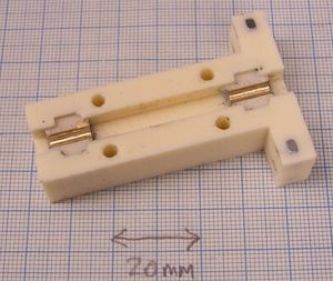
The plastic bearings in the screw holder don't wear much. However, after using mine for a few months I decided to renew the part, and further, I decided to use the old one to make a mould and cast the new one as described here. I then realised that it would be easy to add brass bearings to the moulded part.
First I took a couple of scraps of brass, each with one good flat face and 10 mm deep. All the other dimensions and the quality of all the other faces don't matter much.
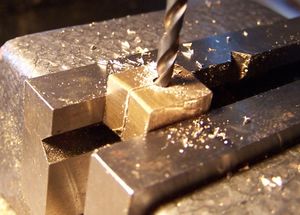
I clamped them in a drill vice with the two good faces together and drilled a 3 mm hole down the join in the 10 mm direction (i.e. the hole was 10 mm long and went all the way through).
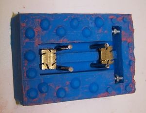
Then I made a silicone mould with cores (this link), with the screw channel in the screw holder at the bottom. I put the two brass bearings in so that the just fitted over the half-round 3 mm diameter projections where the old bearings were. Note the random hacksaw cuts in the backs of the brass bearings. These give a good key for the setting resin.
Finally, I poured polyurethane resin in and allowed it to set. The result was a new screw holder with brass bearings embedded in it exactly aligned (because the old 3 mm channels were aligned).
Sharpened thread
That is the polymer drive screw thread - the sharper it is, the better it will drive hard polymers like polylactic acid and ABS. Sharpen it by running an M6 die down it several times, increasing the screw pressures on the die from the tightening screws in the die wrench. This will result in a slightly undersized thread, but the die will give much sharper peaks than you get on standard studding (which is forge-rolled, not cut).
-- Main.AdrianBowyer - 12 Jul 2008
