Mattroberts' Hot End
Release status: Working
| Description | Stainless Steel Hot End
|
| License | |
| Author | |
| Contributors | |
| Based-on | |
| Categories | |
| CAD Models | |
| External Link |
Introduction
The idea behind this hot end design is to combine the heater barrel and the thermal break into one piece (as nophead has proven can work).
Material Choice
- The combined heater barrel thermal break needs to made out of a material that doesn't conduct heat that much. Stainless steel and Titanium are both good choices - although stainless steel is much easier to source.
- The nozzle needs to made out of a material that expands with heat more than the barrel. Brass is a good choice.
- The insulation can be almost anything, although PTFE plumbers tape is really good and very cheap.
- The heat sink can be made of aluminium - copper would be better still, but harder to source.
Thermal Stuff
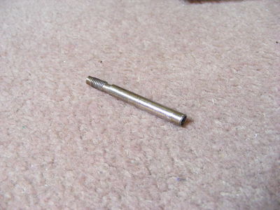
The thermal break / heater barrel starts life as a piece of 5mm diameter, 1mm wall thickness tube.
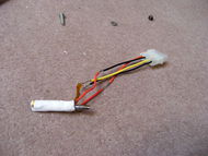
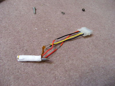
For the heater I wrapped the barrel with kapton tape, nichrome wire, more kapton tape and several layers of PTFE. (Making sure to bury a thermistor inside the PTFE).
Finally, the heat sink (not shown) had a M5 thread and some thermal grease - that way the heat that migrates past the thermal break can be removed. (I also made used an M5 lock nut to keep the hot end stable).
Important features of the design:
- The bore widens towards the nozzle, this means that any plastic that blocks the passage is easily forced downwards. Idea from [nophead's blog].
- The narrow bit of the tube conducts heat poorly enough that the temperature above the narrow is ~30C and ~235C below.
- The heater (in this case: nichrome wire) is placed over the entire length of the tube below the narrow, so that the plastic is molten in the tube proper.
- The melt zone is therefore forced to be in the exposed bit of the stainless - so it is about 6mm long. This means that the rubbery (partially melted) plastic is small enough that it doesn't block the barrel.
Nozzle
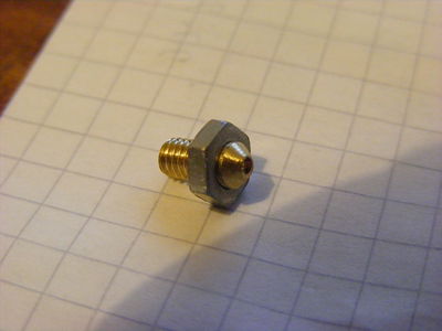
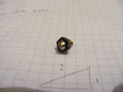
The nozzle is simply a brass M4 screw that has been turned into a nozzle with an exterior M4 thread. Attaching the nozzle to the barrel is easy: just make sure to add some PTFE to the threads to stop any plastic leakage.
The nozzle has a 2mm wide hole until ~1mm from the end, where it is 0.4mm wide. Ideally the hole would be central, and the excess metal around the hole would be much smaller than in the photos.
Because I didn't have a lathe handy to make precise central holes. I made a 1.5mm nozzle and then soldered (with high temperature solder) a claimed 0.3mm (really 0.38mm) pencil lead into the hole. When the pencil lead is removed (mild heating to melt the solder flux, combined with pulling) I got the good clean nozzle in the photo above.
I've also soldered a slimmed M4 nut on to the brass - This means that I can use a socket to attach and remove the nozzle from the barrel. (needs to be done when hot).
Improvements
- Combining this hot end with my cold end means that you can replace the base.stl RP part with a sheet of aluminium acting as the heat sink.
- Replacing the nichrome wire / thermistor combo with a heater block should work - and allow a really short hot end (I guess around 25mm would be doable). The obvious material choice would be copper (it conducts heat really well, and it expands with heat less than the stainless steel).
