OpenSLS
Release status: Experimental
| Description | This is a prototype SLS system designed to interface with a laser cutter to create a platform for experimentation with the SLS process.
|
| License | GPL
|
| Author | |
| Contributors | |
| Based-on | |
| Categories | |
| CAD Models | |
| External Link |
Contents
Project Status
Open SLS is a selective laser sintering project under active development in Dr. Jordan Miller's Physiologic Systems and Advanced Materials Laboratory at Rice University.
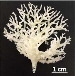
Recently, our lab published our work using OpenSLS for freeform fabrication using nylon and polycaprolactone. You can find the full scientific paper at PLOS ONE. You can find Rice's press release on the project here.
The latest developments to the project can be found on our github page, which includes all of our design files, firmware, and software toolchain.
Introduction
OpenSLS is a platform for exploring the selective laser sintering process and a functioning prototype SLS 3D printer capable of fabricating objects in a variety of materials. It was developed at the Advanced Manufacturing Research Institute (AMRI) and was funded by Dr. Jordan Miller's lab for microphysiological systems and advanced materials. An overview of this project and the research in which it will be used can be found here.
This project is unique in that it appropriates existing, affordable laser hardware, namely laser cutters, for use as in the SLS process. This changed the nature of the challenge from one of procurement (ie, where to find a sufficiently powerful laser and optics) to one of integration, modular hardware design, and material development. The openSLS hardware is designed to be a drop-in powder management module whose sole purpose is to synchronously lay out layers of powder for the laser motion system (the laser cutter's gantry and laser) to sinter or melt. By adapting commercial and widely available laser cutters for this process, the barrier to entry for this technology can be lowered.
SAFETY
Because SLS is an inherently high-energy process involving a powerful invisible laser, CNC equipment, and hazardous materials, it should not be treated like the more familiar extrusion-based machines. This is a very dangerous process. Much can go wrong. If you decide to explore this technology, please exercise extreme caution: the potential for lasting bodily harm is real and ever-present and should taken very seriously.
Laser Safety
The lasers used in laser cutters are incredibly powerful-- literally tens of thousands of times more powerful than the pocket laser pointers that already bear a eye-safety warning label. This is a whole other class of laser safety. Your eyes are no longer the only thing at risk. In addition to the danger of the laser radiation, the gas tube that emits the laser is driven by a high voltage power supply with voltages upwards of 30kV. Extreme care should be taken when working on the laser cutter electronics as the high voltage supply holds charge for some time after the laser cutter is powered down. Sam Goldwasser has prepared an excellent page on laser safety, including an extensive section on DIY lasers and the safety challenges there-in. Please read through it before attempting any of the work described here.
Materials Hazards
Finely powdered materials are often VERY FLAMMABLE or EXPLOSIVE in addition to being a serious respiratory hazard. Extreme care should be taken when handling powdered materials. Static shocks are in some cases enough energy to ignite clouds of dust, causing an explosion. Additionally, this first prototype does not incorporate inert-gas shielding of the powder-laser interface, which, for some materials, could be very dangerous, especially if any powder becomes airborne.
Process Overview
Laser-based additive manufacturing technologies are a little different from the more familiar melt-extrusion techniques. Of chief interest is the flexibiity that comes with using a powdered feedstock. Many non-thermodecomposing materials have the potential for compatibility with the laser-forming processes.
Terminology
The term SLS is used often broadly to describe a number of laser-forming processes. It is sometime distinguished from selective laser-melting (SLM) because there is a clear difference between the two solidification methods. Laser-melting involves fully melting the powdered material to its liquid phase, which results in a fully-dense part. Laser-sintering relies on very high thermal gradients to liquify (though not in all cases) the surface of the powder particles, bonding to each other, but leaving small voids between the bonded particles. In terms of bonding mechanisms, this distinction is important, but in terms of terminology, laser-sintering and laser-melting are often used somewhat interchangeably. Kruth et al, 2005 proposed 12 distinct binding mechanisms in the family of laser-sintering/laser-melting processes. The important point though is that the distinction between mechanisms is mainly material-dependent and based on particle size, geometry, packing structure, and thermal conductivity as well as the bed temperature, laser power, spot size, and atmosphere. But the implications of the finer points of laser-forming terminology with respect to this project are interesting: this system has been demonstrated successfully with the laser-melting process, but has yet to be demonstrated with the laser-sintering process.
Mechanics
The process of laser-sintering begins with a very simple system: a laser injecting energy into a group of particles of some mass. However, many factors influence how the laser energy is absorbed: particle shape, size, packing density and configuration, material absorption, reflectivity, and transmission, atmosphere, energy density, beam profile, and spot diameter are some of the major factors.
The particle shape affects how the powder behaves at a macro scale: spherical particles flow easily over each other and en masse yield powders that flow much like a liquid. More angular particles give rise to transient, but stable packing structures and flow in more staggered, halting ways on the macro scale. Flakes and more complex platelets can have both fluid flow properties in some cases, a degree of self-adhesion or self-entanglement, depending on the complexity of the form of the particles. These geometric factors combine with particle size to influence particle packing patterns, which in turn play a large role in how heat is transferred through the particle system at the site of sintering. Heat transfer between bodies is proportional to both the magnitude of the temperature difference and the cross-sectional area between the bodies. Particle size, shape, and packing pattern determine the number and size of contact points between particles (Gusarov et al, 2003). The more points of contact there are between particles, the better heat can flow through them.
In addition to influencing heat transfer through static powder, particle size and shape (and distribution there-of) affects how laser energy is transferred to the powder particles. The surface of the powder bed can be thought of as porous-- there are numerous voids between particles that expose particles one or two layers deeper in the bed to the laser. This changes the absorption topology: for a solid material, laser energy would be absorbed through the two-dimensional surface of the sample. Here, laser light penetrates deeper into the material, both reflecting off of and being absorbed by particles beyond the surface layer (Simchi, 2006).
Now we can begin to consider the impact of time on the system. As the laser heats particles in a three-dimensional profile, the surfaces of the particles begin to melt, increasing the contact surface are between individual particles and through bonding and eliminating the material-gas-material junction, increasing heat transfer between particles. This can be though of as a changing of the rate of sintering which is in turn dependent on the rate of sintering (Simchi, 2006). In other words, sintering accelerates itself due to the increase in heat transfer that occurs as particles begin to bond to each other.
In the case of laser-melting, there is a full phase change from solid to liquid, which gives rise to one of the most difficult challenges in laser-sintering/-melting processes: the "balling effect," which describes the tendency of powdered materials to bead up into small spheres after being heated by the laser beam. This is a result of surface tension evolving and exercising a shaping force upon the material as it is liquified. The effect is very similar to the segmentation that a single stream of water undergoes as it falls– the tension distributed over its cylindrical surface is uneven, spatially speaking: the surface tension creates a constrictive force, which due to natural variances in the shape of the stream, leads to necking, which leads to drop formation. The drops assume their spherical (or nearly spherical) shape because it is the lowest energy shape for the physical system: net tension is the lowest. The same forces that create drops from a shower head are responsible for the small drops of material in the balling effect.
Hardware
Progress in open-source laser-sintering technology has been stymied by a lack of affordable, high-power laser sources and optics chains. Laser cutters are increasingly accessible at hackerspaces and are rapidly dropping in cost. By using an existing high-precision gantry and associated optics, laser source, and power supply, the most significant barrier to entry into this technology can be removed. OpenSLS is a relatively simple powder-handling module that drops into a laser cutter to create a platform for laser-sintering research. The powder module was designed to consist largely of laser-cut parts to allow it to be fabricated upon the laser cutter whose functionality it will augment. 3D printed parts are also used extensively and nearly all other hardware can be sourced from McMaster and Inventables. Multiple modules can be installed into one laser cutter, allowing for tandem experimentation in multiple materials.
Powder Module
R1 Hardware
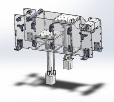
The R1 powder module consists of two pistons of identical dimensions, each driven by a lead-screw of different pitch. The feed piston is driven by an M12x3.0 Acme screw while the print piston is driven by a M8x1.25 threaded steel rod. The difference in pitches was intended to allow the two pistons to be driven off the same motor control channel in a direction-reversed parallel configuration, moving different distances simultaneously in opposite directions. However, the "transfer ratio" between the pistons is actually quite dependent on the material in quesiton as well as, to some degree, the geometry of the object to be printed.
The R1 powder distributor first used a cable-driven counter-rotating anodized Aluminum rod to spread print powder during layer distributions. Tensioned nylon monofilament wrapped around static pulleys coupled to the ends of the distributor rod enforced counter-rotation during translation, which was accomplished by belt-driven bushings at each end of the Aluminum rod. This allowed for a one degree drive to effect two degrees of motion. Later experiments indicated that a much simpler powder distributor perfromed better than the counter-rotating one. A stainless steel lab spatula provided the best results in both wax and nylon. While the powder distributor uses two stepper motors (solely for the lack of an appropriately-sized GT2 timing belt), these too can be driven in parallel to reduce again the number of motor channels needed to control the system.
R2 Hardware
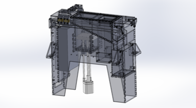
The second revision of the hardware addresses both mechanical issues relevant to the laser sintering process and usability considerations with the following features:
- Aluminum build chamber compatible with silicone heating pads
- Inert gas build volume shielding via perforated build plate
- Level-able build plate
- Fluidized bed part extraction
- Modular and adaptable distributor system
- Integrated electronics and power supply
- Internal powder capture and storage
- Linear motion hardware better isolated form powder
- Adjustable powder distributor blade
- Properly constrained distribution system on linear rails to enforce layer height
- Integration brackets for securing powder module to laser cutter frame
- Modular construction for easy cleaning of the powder ducting and print piston
- Integrated distributor wiper cleaning brushes to dislodge any adhered clumps or powder
- Module is free-standing when removed from the laser cutter for easy maintenance/repair
Laser Cutter
The laser cutter was procured through SeeMeCNC. It is a nameless Chinese import system with an 80W tube, a 600mm x 900mm work envelope, and surprisingly capable accompanying software. Any laser cutter that uses stepper motors (and that's most of them) should be compatible with the electronics stack used here.
Laser Power
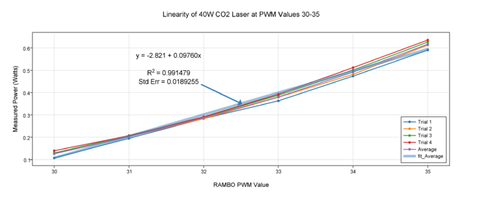
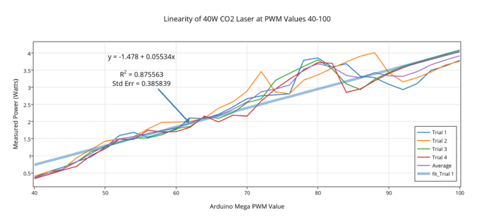
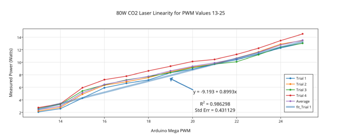
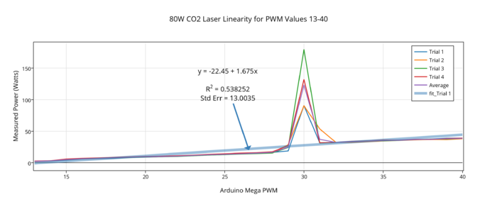
Both an 80 Watt and 40 Watt tube were tested for use with the OpenSLS powder module. Both tubes only emitted above a threshold current level, creating a firm lower bound to the power levels that could be explored. The lowest attainable power was 2.4 Watts on the 80 Watt tube and approximately 100 milliWatts on the 40 Watt tube. As can be seen below in the plots of laser power versus PWM control signal value, linearity varies depending on power range. Both tubes exhibit higher variability at higher output powers, though the 80W tube distinguishes itself by a power surge between 14 and 40 Watts, during which it reaches powers measured over 150 Watts before returning to a more predictable linear regime. The lower end of the 40W tube's power range allowed for the finest graduation of power levels for exploring relatively low laser power carbohydrates and polymers.
BOM
The BOM can be found on github.
Print Materials
One of the powerful aspects of laser sintering is its ability to fabricate parts out of many different materials. This system has been tested with a relatively small number of materials to varying degrees or rigor, from simple point-melting to one dimensional trace sintering, all the way to full three dimensional sintering.
Methods of Fabrication
Granular Crystalline Powders
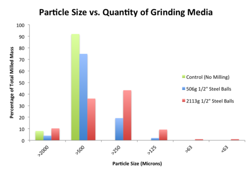
Ball-milling is a widely-used process for reducing particle size for brittle and crystalline materials. The laser-sintering process requires fine particles for even trace formation and higher resolution, but many materials are only available as coarse grains. By ball-milling and sieving the results, fine powders of homogenous particle size can be manufactured in small quantities. I used a small rock tumbler to start making powders and graduated to a high-capacity tumbler with a steel barrel for making larger batches of powder using larger grinding media.
As can be seen in the two charts below, there are two governing trends in grinding media selection. First, a higher ratio (by weight) of grinding media to substrate yields higher fractions of finer particles. Second, larger grinding media "grains" out yield higher fractions of finer particles than do smaller grinding media or mixtures of small and large grinding media. Both of these trends make sense in the context of the countless tiny impacts between grinding media and particles that constitute the ball milling process: higher mass grinding media lends lends delivers higher energy impacts and more grinding media means more impacts.
Wax-based Powder
Candelilla wax can be purchased from Strahl and Pitsch. For printing with low power near IR laser diodes, it is necessary to blend a small amount of carbon powder into the wax to act as an energy absorbing pigment. The mixture can be prepared by blending 100 parts wax with 7 parts carbon by weight and then working the mixture through an 80 mesh sieve to thoroughly break up wax clumps and incorporate the carbon. This mixture is sensitive to humidity and begins to clump after remaining static for several days.
Candelilla Wax
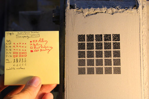
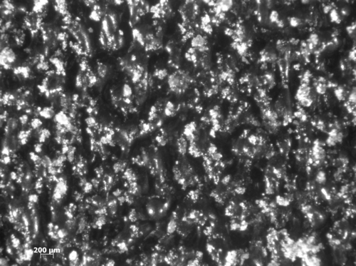
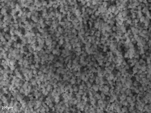
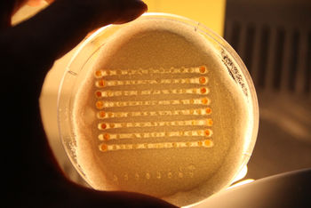
Candelilla wax has been demonstrated as as a potential low-cost SLS print material and was investigated as a positive control during OpenSLS hardware development. The print material consists of Candelilla wax and carbon powder blended in a 100 to 7 ratio, in which the carbon powder acts both as an energy-absorbing pigment for laser wavelength in the near infrared and also as a de-clumping agent. The laser-sintering previous demonstrated in 2011 by Andreas Bastian was full-melting laser consolidation, which leads to high amounts of curling and lower edge definition due to surface tension effects of a fully-liquid consolidation zone. Parameters for more traditional liquid-phase sintering of individual particles were investigated via traversal of the power/speed parameter space. Of the 325 power/speed combinations attempted, none yielded liquid-phase sintering between individual particles of wax. Instead, imaging of 2D sintered surfaces indicated a fine degree of balling sufficient to lead to binding between small consolidated regions of particles, leading to a bulk cohesion sufficient for printing delicate and porous objects.
Nylon
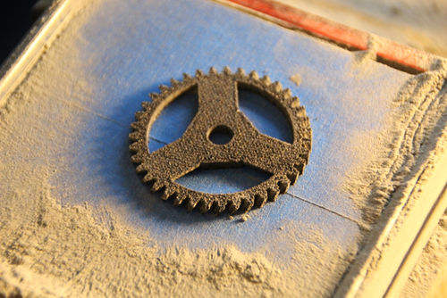
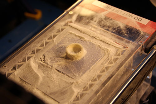
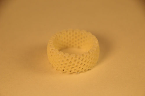
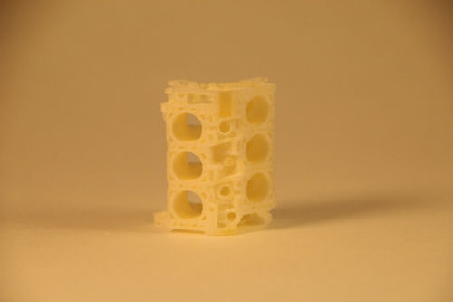
Samples of Taulman 618s and PA 650 were procured from Taulman3D and ALM LLC, respectively. Both nylons proved much easier to sinter than the wax or the isomalt. Like the wax, the first layer needed to be firmly bonded to the build platform (blue tape, in this case), or else curling would disrupt powder distribution and layer registration. Even so, unsupported regions of the printed object will curl and disrupt the print later in the print sequence if of sufficient size to catch the distributor blade. Adhering the first layer of the print is a work-around to allow for further exploration of 3D sintering, but it does not allow for the same freedom from geometric constraints as commercial SLS techniques. This will have to be achieved via heating the powder under an inert atmosphere.
These early objects were fabricated with a laser power of 400mW, print speed of 58mm/s, layer height of 150 microns, and "nozzle" size of 0.075mm. See the PA650 slic3r profile in the OpenSLS github for more detailed process parameters. This power level is quite low and obviously the CO2 laser can emit at much higher powers. What's important is the high absorption efficiency of nylon at 10.6um, the wavelength of CO2 gas lasers. Low cost, high-power diode lasers are in the near infrared range, between 808nm and 840nm, which is not easily absorbed and converted into heat by nylon. Lasers in the blue range may have better absorption. Adding an energy absorbing pigment, such as carbon in the above Candelilla wax mixture, may be effective for diode laser implementations.
Silica/Sand
Silica sand shows promise as a cheap and abundant print material. As demonstrated by Markus Kayser, sand can be thermally fused into objects of some functionality. Further exploration beyond this simple test of sinterability is necessary.
Sucrose
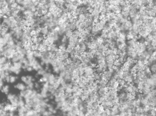
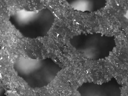
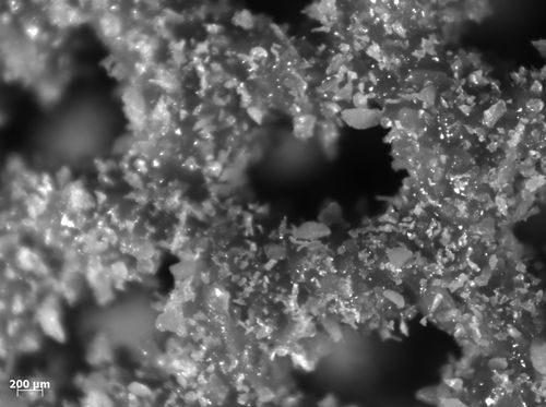
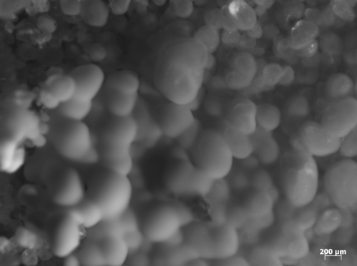
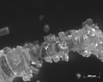
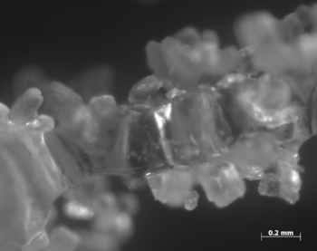
Sucrose exhibited poor sintering characteristics when tested with readily available table sugar under regular atmosphere. It smoked, balled, and caramelized under the laser, but in some cases was able to be sintered into continuous traces by repeated scanning with the laser.
The most successful (though basic) sintering was achieved with a laser power of 2.4 Watts at 125mm/s with ten sequential linear scans, which produce the sintered column in the above magnified images.
Electronics
The electronics that drive this system are a mix of native laser-cutter modules, 3D printer electronics, and 3rd party components. The main modules are as follows:
- Rambo Board
- Laser cutter stepper drivers
- Laser Power supply
- Arduino Uno (any Arduino will work though)
- Powder module stepper drivers
RAMBo Board
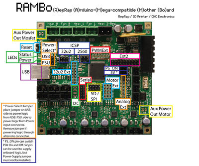
The Rambo is extremely well-documented board that can be adapted to drive diverse CNC equipment and with the appropriate firmware, is an excellent tool for hardware development. Here, the X and Y step, direction, and enable pins are re-mapped to the motor ext pins (see right) and routed to the step, direction, and enable pins on the Leadshine stepper drivers (see below) used in the laser cutter.
Native Laser Cutter Electronics
The laser cutter's electronics stack is very modular and very hackable. Everything is connected via Molex connectors and, with the exception of the laser power supply, is clearly labelled. Due to the low melting point of the materials that I am targeting for research in tissue engineering and regenerative medicine, I replaced the 80W tube and power supply that shipped with the laser cutter with a lower power 40W tube and 40W power supply to provide higher power resolution at the lower end of the power spectrum. Additionally, the 80W tube would not laze below 2.5 Watts, which was right in the middle of the power range that proved to be best for sucrose and wax materials. The 40W tube and power supply can deliver power as low as 200mW, which is useful for the wax material.
The laser cutter power supply has a decent manual, though the manufacturer uses the manual for 20W, 30W, 40W, 60W, and 80W systems, so disregard the maximum current specified-- the 40W tube that I am using from Technologies shouldn't be run above 10-12mA for extended periods of time. Doing so will dramatically shorter the tube's life. I also tried to use a [40W power supply http://www.automationtechnologiesinc.com/products-page/laser-engraving/new-40w-co2-laser-power-supply] from Automation Technologies, but was alarmed by the lack of a clear cathode. John Oly from SeeMeCNC was kind enough to take a look at the wiring on a 40W laser cutter purchased from Automation Technologies and found that the laser cathode was case-grounded via a massive, un-marked power resistor. Not wanting to take any risks with the 30kV wiring, I opted for a power supply instead from Light Object instead because it a) had documentation, b) had a clear anode and cathode, and c) the open source laser cutter community over at Buildlog.net seems to have had good experiences with LightObject.
The wiring wiring diagram for PWM control is shown at left. While the manual specifies a minimum pulse width of 1ms and datasheets for similar low-cost CO2 laser power supplies spec a 20kHz PWM frequency, the power supply can be driven with the native ~490Hz PWM frequency of the RAMBo. Please exercise extreme caution when working with the laser power supply. It holds a high voltage charge even after it has been powered down. I have verified this by coaxing a high-power beam out of the tube after shutting power off to the laser power supply.
Powder Management Arduino
This Arduino is entirely not necessary and is solely a reflection of time constraints and my difficulties in refactoring Marlin into a more generic 5-axis state. The RAMBo has 5 fully functional motor channels, but I found it difficult to untangle the two channels used for extruder control from the many optimization and safety features in Marlin. I encourage those with more experience in firmware development to tackle porting a stable RepRap firmware to run SLS hardware. The powder management Arduino runs relatively simple code to increment the Z-axis and distribute new layers of powder, which can be found here. The Arduino uses two stepper drivers to run the four stepper motors used in the powder module.
Integration
The most important part of integrating the RAMBo board with the laser cutter electronics is to make sure that all connections share a common ground. I chose not to rig an interface with the laser cutter's native inductance-based transistor endstops and instead mounted mechanical endstops that were compatible with the RAMBo. I also maintained the laser cutter's control over its Z-axis, which was useful for auto-focusing on the powder bed. Once focused however, there is little need for the laser cutter's native microcontroller.
Software
The main challenge I encountered here was adapting firmware developed for melt-extrusion machines to run a 5 axis machine with a different geometry. Before switching to a secondary microcontroller for powder module control, I attempted to use the extruder channels to drive the feed and print pistons individually and to use the Z channel to drive the distributor. I also experimented with running the z-axis on the z-channel and wiring the two distributor motors in parallel to run off one extruder channel. In both cases, I ran into difficult to trace motion control bugs, such as varying speed, incorrect travel distances, and one-directional motion on the extruder channel. I disabled many of of the safety features that regulate extruder behavior in Marlin, but I must not have found them all. In the interest of making progress on the larger goal of laser-sintering, I slaved an Arduino Uno to run the powder module. Again, this is only due to the difficulties that I encountered adapting Marlin to this hardware. A more generic 5-axis firmware running on RAMBo, RAMPS, or any other 5-axis CNC controller should work. My fork of jmil's fork of Marlin can be found here and includes code to run the slaved Arduino. I established control over the laser firing and timing by comparing previous and current extrusion distances, much in the same way that retraction is controlled.
The hardware can be run both standard RepRap tool chains and with Python-scripted GCode. I am currently slicing with Slic3r and using Pronterface. The slicing parameters need to be modified to reflect the optimal sintering parameters (print speed, "nozzle"/spot diameter, layer height) for the material at hand and GCode to move the laser head out of the path of the distributor and to initiate the distribution sequence needs to be added to the "Layer Change" GCode under Printer Settings/Custom G-Codes. Here is an example of possible layer change code:
G4 S2;  Pause for a couple of seconds to allow any buffered motions to finish
G91;  Switch to relative motion for a moment
G1 X-200;  Move the laser head out of the way
M700; Run powder hardware
G4 S13;  Takes 13 seconds to do the layer change
G1 X200;  Move the laser head back to its original position
G90;  Back to absolute positioning
G4 S2;  Give the laser head a couple sconds to get to position
Videos
<videoflash type="youtube">iH88olts46o</videoflash>
<videoflash type="youtube">ef427AYVZiw</videoflash>
<videoflash type="youtube">-qbLxL3KBKE</videoflash>
<videoflash type="youtube">0XuoxrC6cec</videoflash>
<videoflash type="youtube">4SZpGtWF-hY</videoflash>
Source Files
Source files are hosted on github. While this design is functional, it is by no means optimized. There are numerous improvements to be made and I encourage anybody who is interested to iterate upon and improve this and subsequent designs.
Future Work
The next prototype is under active development and features heated Aluminum pistons and basic positive pressure inert-gas shielding for further experimentation with nylons, metals, and hygroscopic materials. Progress can be tracked on Andreas Bastian's dev blog.
See Also
- The Focus SLS Printer is an impressive machine that can be assembled out of MDF and printed parts.
- Andreas Bastian's original SLS printer on which this project is based.
- Peter Jensen's early explorations of SLS printing that included the development of a low-cost reciprocating laser cutter.
- Another way to build a SLS 3D powder printer using RAMP's and Marlin Simple build!
- While not strictly an SLS machine, the PWDR printer is a nice powder handler.
- You SLS is an Indiegogo-backed, open-source SLS design using RAMPs
Further Reading
- Simchi, A. (2006). Direct laser sintering of metal powders: Mechanism, kinetics and microstructural features. Materials Science and Engineering: A, 428(1-2), 148–158. doi:10.1016/j.msea.2006.04.117
- Kruth, J.-P., Mercelis, P., Vaerenbergh, J. Van, Froyen, L., & Rombouts, M. (2005). Binding mechanisms in selective laser sintering and selective laser melting. Rapid Prototyping Journal, 11(1), 26–36. doi:10.1108/13552540510573365
- Gusarov, a V, Laoui, T., Froyen, L., & Titov, V. I. (2003). Contact thermal conductivity of a powder bed in selective laser sintering. International Journal of Heat and Mass Transfer, 46(6), 1103–1109. Retrieved from http://linkinghub.elsevier.com/retrieve/pii/S0017931002003708
