OpenX
Release status: working
| Description | a minimal X carriage that uses bearings
|
| License | GPL
|
| Author | |
| Contributors | |
| Based-on | |
| Categories | |
| CAD Models | |
| External Link |
The Goal here is to create a lightweight, minimal x carriage. the carriage will have a large central opening to facilitate various hot end designs, and provide enough room to insulate the hot end.
I find the default Sells carriage too bulky and confining. I also hate that the mounting points are above the rails, which means the whole carriage has to be disassembled if you want to get to the extruder because the captive nuts often fall out anyway. It also has a lot of mass, and much of the structure is bellow the rails, putting it close to the hot end and risking warping from the heat plume.
Contents
BOM
New RP Parts
- 1 x Carriage
- 1 x Arm
- 1 x Undercarriage Bracket
Nuts and Bolts, Standard Parts
- 12 x M4-16 screws
- 12 x M4 nuts
- ~30 x M4 washers
- 9 x 624 Ball Bearings
- 1 x X-Axis opto flag
- A package of zip ties
Assembly
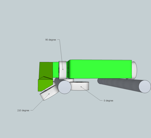
In order to make construction easier, i didn't oppose the bearing by 120 degrees each, instead opting for a 0, 90, 210 degree config.
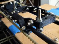
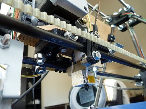
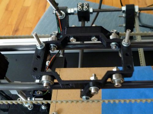
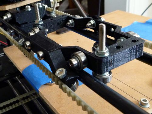
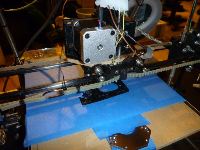
rather straight-forward if you just look at the pictures. minor tightness/alignment adjustments can be made by adding or subtracting washers next to the bearings or between the carriage and arm.
These pictures are of the prototype, but are clearer as there is less complexity to the parts.
Those m4-40 bolts are all that i had that would reach, but this has since been fixed by reversing the screws and recessing the screw heads.
Arm and Undercarriage Bracket
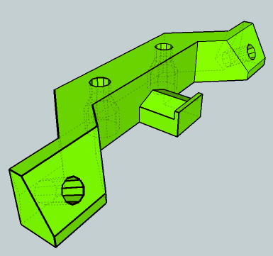
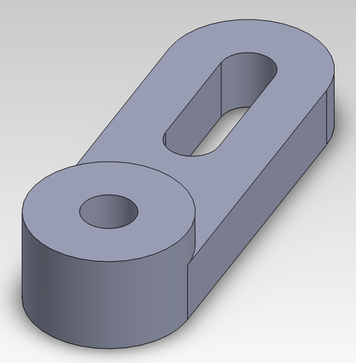
put a bearing on each end of the arm part. you can use a washer on each side of the bearing, but you can probably get away with only one washer between the bearing and the plastic. You probably will not be able to get a washer on the nut side.
For the undercarriage bracket, the bearing goes in the hole, not the slot. you probably need 2 or three washers between the bearing and plastic for proper alignment.
Carriage
for the four 90 degree bearings, i added 2 washers as spacers.
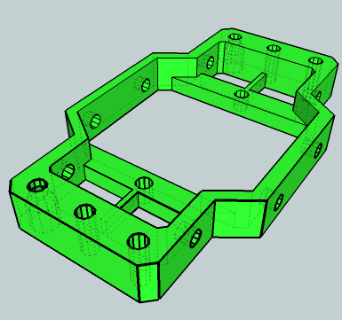
The screws for the two 0 degree bearings go into the large holes on the surface of the carriage so that the heads get recessed. obviously, there are no washers on this side. I used 3 spacer washers for these bearings.
The tricky part here is opto flag. it will depend on which side of the belt you attach the carriage to. the easy way to do this is to attach the flag to one of the free holes opposite the 0 degree bearings. However, the point at which the belt attaches to the carriage is on the arm side (which is also the same side as the 0 degree bearings). What this meant for me was that I'd have to reverse the x axis motor in your firmware in order for the x axis to home. I didn't want to do that at the time, so i just put the opto flag on the same bolt as the 0 degree bearing. it was not recessed, which might make mounting some extruders difficult.
Attach the arm on the side with the 0 degree bearings. The screws that attach arm are also recessed into the arm bracket.
Mounting to the X Axis
The arm side of the assembled carriage will just clip onto the rail. Verify that this works without too much force before attaching the extruder. If it is too tight, you can try adding some washers between the arm and carriage. Also check that the bearings are centered on the rails, and add or subtract washers until they are close enough to centered. adding spacer washers to the 0 and 210 degree bearings might alter the force of attachment, so always recheck after adding or removing bearings.
attach your desired extruder. I designed this carriage for a Wade's extruder, but i wanted it mounted parallel to the axis. I think this might actually turn an Adrian's extruder sideways, and i have not tested it with an Adrian's extruder for clearance between the mendel frame, so please note this if you intend to mount an Adrian's extruder. the undercarriage bracket can be loosely attached to the carriage and swung down into place once the carriage is on the rails, but this is often more trouble than it is worth, at least with 16 mm screws, since it just barely clears the rail. I might have to eventually make this a captive nut, as it can be hard to get tools under the carriage when the extruder is mounted. Tightening the attachment screw will torque the arm upward and snug the bearing up against the rail.
(should I add a second attachment screw to the undercarriage bracket? As it is currently, it holds adequately for normal printing, but a moderate force can move the arm. I like this because if the extruder head crashes, it will probably be enough force to move the undercarriage bracket, so it acts like a safety preventing damage to the hot end. If other people notice that it loosens up too often, I can design a sickle shaped bracket instead, like suggested below in Variations)
The belt just slips around the tooth that juts out the bottom of the arm. This forms a bite in the belt, and when it's properly tensioned, grabs the carriage securely.
Pictures and Files
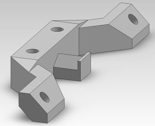
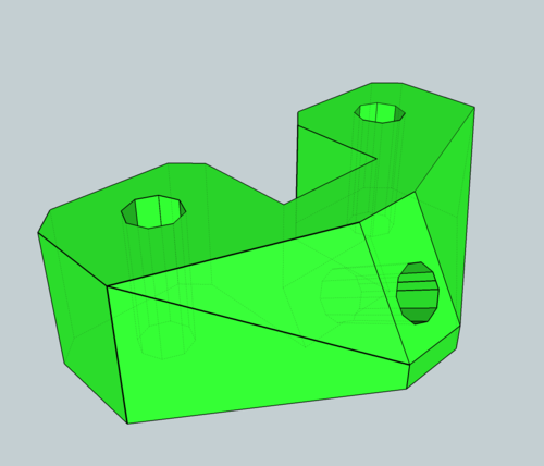
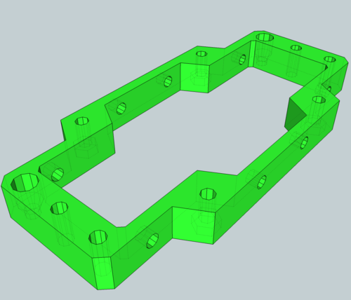
here are some pictures of the individual parts along with the files: (Modeled in sketchup. The STLs are in this zip file(File:OpenX Carriage Full Set.zip), or can be found on thingiverse.) You can follow my progress in the forum here. Please make suggestions!
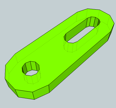 File:OpenX Undercarriage Bracket.skp
Variations
The Arm was redesigned by PSU RUG [1]. The angle the bearings contact the horizontal rod was changed from 30 degrees below horizontal to 45 degrees below horizontal. This helps prevent the carriage from "walking" up the rod. The arm was also re-dimensioned so the carriage fits 5/16 inch rods.
The undercarriage bracket was also redesigned by PSU RUG. The bearing on the bracket is now aligned with the vertical bearing on the carriage. This bracket will also fit on the Open-Y carriage.
It was requested I make up an Arm bracket with only one bearing. However, I didn't design into this a way to attach the belt, so nobody should print it. it needs an outrigger or two that you can bind the belt behind.
It was also requested I beef up the undercarriage bracket, making it into a sickle-like shape. I still need to model this up and so will post this later
EtherDais requested a dual-extruder design for the OpenX, so I whipped up this little number. This is built to accommodate two wades extruders, so i had to put them perpendicular to the axis. it's probably best to mount them with the gears facing each other, which will probably reduce build area/height over the regular OpenX (but probably similar to a Sells carriage).
I could make the design a more compact if the intent is to use two or more bowden extruders. Or even one Wades and one Bowden. anyway, I haven't printed this out, so any feedback is appreciated, if you do decide to try it.
you assemble it exactly as a regular OpenX, except that the mounting points are captive nuts. (I hate that they are right above the rails, but at least it is easy to remove the carriage to mount extruders.) the arm will fit just fine. however, the undercarriage bracket sticks up a tiny bit above the top of the carriage, so that might need to be filed down a bit. also, make sure the bearings are running clear after mounting the extruders. If they rub against the bottom of the extruder I'll move the surface up a mm or two.
- File:OpenX Dual Wades.skp
- The .stl as a zipped file File:OpenX Dual Wades.zip
