Mendel X-axis
Mechanical: Overview | Mendel solid model files | Procurement | Preparation of materials | Assembly notes | Extruder | X-axis | Z-axis | Y-axis | Circuit boards | Frame | Squaring the axes
You may find the Mendel assembly data sheet useful during assembly.
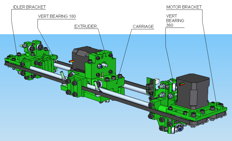
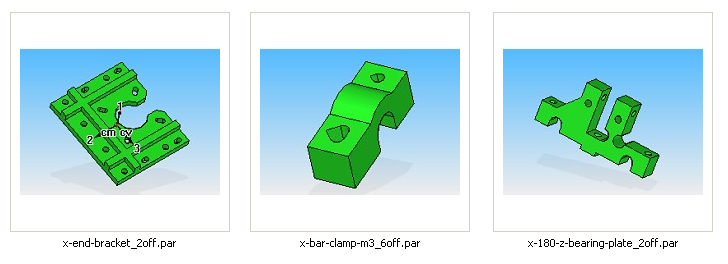
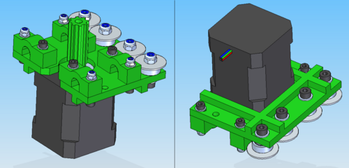
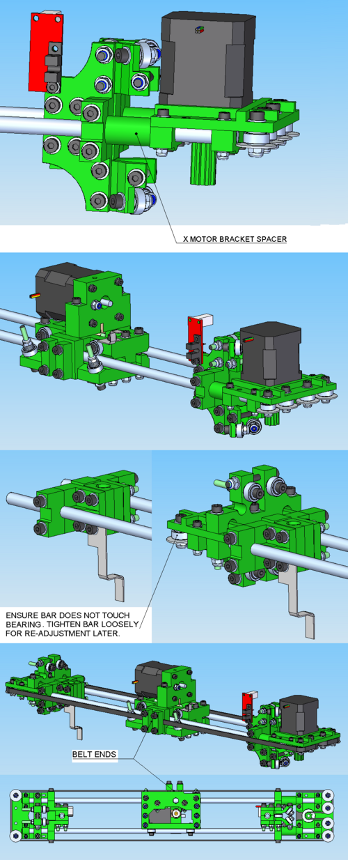
This diagram shows the main components of the X axis. N.B. there is an alternative X motor bracket design that reduces stress on the X belt that you may want to consider using. With the original design the x-belt only lasts for about 100 hours because it bends back on itself through too tight a radius for a T5 belt. If you have bought a set of parts and find you are missing one x-end-bracket_2off, then you probably have the updated version.
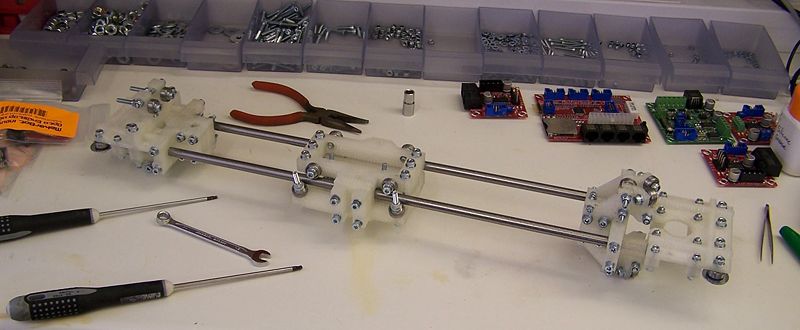
This shows the X axis almost completed. The opto-switch and opto-switch flags haven't been fitted, and nor have the motor, the extruder, and the toothed belt.
This video shows the working principals of the Mendel X axis, it may be useful for you understand how it performs:
Contents
Carriage
BOM
Total # of assemblies: 1
| Name | Qty/assembly | Total Qty | Type |
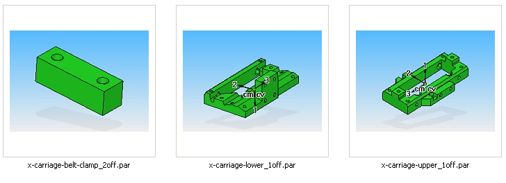
| x-carriage-belt-clamp_2off | 2 | 2 | RP |
| x-carriage-lower_1off | 1 | 1 | RP |
| x-carriage-upper_1off | 1 | 1 | RP |
| m4-nut | 12 | 12 | Fastener |
| m4-nylock | 10 | 10 | Fastener |
| m4-washer | 58 | 58 | Fastener |
| m4x16-cap | 6 | 6 | Fastener |
| m4x40-cap | 14 | 14 | Fastener |
| x-flag | 1 | 1 | Thin sheet |
| 624-bearing | 10 | 10 | Bearing |
Reprapped parts
Assembly
Before this assembly it's important to understand the key mechanical concepts of how the axes work. If you haven't already, check this video out:
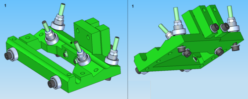
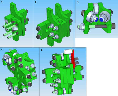
Assemble the lower carriage first (1). Note trapped nuts. If you prefer you can use 25mm M4 screws for the inner ball races (facing towards you in the picture and projecting upwards), rather than 40 mm. This will make the axis more compact, but will increase the number of different screw sizes in the machine. Leave the outer ones as they are in the picture at 40 mm - they are sometimes used as mounting points for various add-on devices. Note that the build sequence is bolt-washer-carriage-washer-bearing-5 washers-nylock nut.
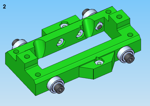
Then assemble the upper carriage (2).
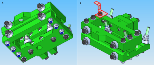
Assemble the two halves together (3) using 6 M4x40 caps (don't forget the optoflag!). Tighten the middle two caps, keep the outer two pairs loose. When fully assembled use a piece of ø8 mm bar to set the distances between the bearings. Slide the bar between the bearings and tighten/slacken the outer two pairs of M4x40 caps to achieve a smooth, low resistance, running fit.
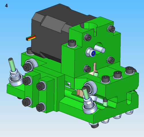
Finally assemble the extruder (4).
Put one of the X-axis rods down the 3-bearing side of the carriage. It should be loose or just tight, and it should run freely. If it's tight (even though you have not yet tightened the adjusting bolts), then take the two halves of the carriage apart and put M4 washers between the pillars that hold them apart. Get it running either just loose, or touching but freely-rolling.
Idler bracket
BOM
Total # of assemblies: 1
| Name | Qty/assembly | Total Qty | Type |
| x-180-z-bearing-plate_2off | 2 | 2 | RP |
| x-bar-clamp-m3_6off | 2 | 2 | RP |
| x-end-bracket_2off | 1 | 1 | RP |
| m3-capx20 | 4 | 4 | Fastener |
| m3-nylock | 4 | 4 | Fastener |
| m3-washer | 8 | 8 | Fastener |
| m4-nylock | 11 | 11 | Fastener |
| m4-washer | 36 | 36 | Fastener |
| m4x16-cap | 2 | 2 | Fastener |
| m4x40-cap | 9 | 9 | Fastener |
| m5-mudguard-washer | 2 | 2 | Fastener |
| 624-bearing | 6 | 6 | Bearing |
Reprapped parts
Assembly
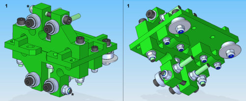
Do not tighten the two adjuster bolts marked with a * in this diagram. These will be used to set the contact between the bearings and the Z shaft. If you attempt to tighten them now you may damage the bracket. N.B. there are 3 washers under each of the four z-axis bearings, and each mudguard washer has an ordinary M4 washer between it and its bearing.
Vert bearing 180
BOM
Total # of assemblies: 1
| Name | Qty/assembly | Total Qty | Type |
| z-flag.par | 1 | 1 | Thin sheet |
| x-axis-side-plate-nut-jig_2off | 1 | 1 | RP |
| x-bar-clamp-m4_4off | 2 | 2 | RP |
| x-vert-drive-nut-trap_4off | 2 | 2 | RP |
| x-vert-drive-side-plate-180-end_2off | 2 | 2 | RP |
| m4-nut | 4 | 4 | Fastener |
| m4-nylock | 4 | 4 | Fastener |
| m4-washer | 16 | 16 | Fastener |
| m4x40-cap | 8 | 8 | Fastener |
| m8-nut | 1 | 1 | Fastener |
Reprapped parts
Assembly
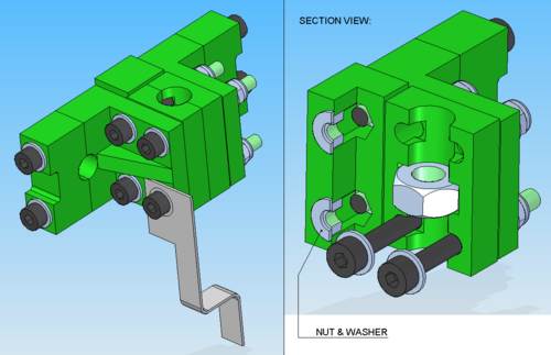
Use the ‘side plate nut jig’ to trap the nuts for the bar clamp bolts. There is room between the jig and the side plate for washers on both sides.
The easiest way to secure the nuts in the nut jig is to attach the clamps to each side plate first. Once tight, the nuts can be aligned to the shaped holes in the nut jig. Next, thread the bolts through the side plate and nut trap, and slip the nut jig over the nuts. Now thread the other side plate onto the bolt ends. minor misalignment of the last two nuts can be corrected with some tweezers or needle nose pliers
Note that if the 4 clamp bolts are completely removed, the nut jig will fall out of the assembly. This should be avoided as it is nearly impossible to get the washers back in place once it is fully assembled.
Vert bearing 360
BOM
Total # of assemblies: 1
| Name | Qty/assembly | Total Qty | Type |
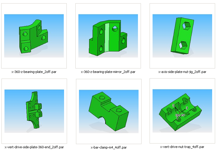
| x-360-z-bearing-plate-mirror_2off | 2 | 2 | RP |
| x-360-z-bearing-plate_2off | 2 | 2 | RP |
| x-axis-side-plate-nut-jig_2off | 1 | 1 | RP |
| x-bar-clamp-m4_4off | 2 | 2 | RP |
| x-vert-drive-nut-trap_4off | 2 | 2 | RP |
| x-vert-drive-side-plate-360-end_2off | 2 | 2 | RP |
| opto-endstop-v2-1-pcb | 1 | 1 | PCB |
| m3-capx20 | 1 | 1 | Fastener |
| m3-nylock | 1 | 1 | Fastener |
| m3-washer.stl | 2 | 2 | Fastener |
| 624-bearing | 6 | 6 | Bearing |
| m4-nut | 4 | 4 | Fastener |
| m4-nylock | 14 | 14 | Fastener |
| m4-washer | 44 | 44 | Fastener |
| m4x16-cap | 4 | 4 | Fastener |
| m4x40-cap | 14 | 14 | Fastener |
| m8-nut | 1 | 1 | Fastener |
Reprapped parts
Assembly
As with the Vert Bearing 180, there is room between the nut jig and the side plate for washers on both sides.
Motor bracket
See also: Mendel Alternate X Motor Bracket
BOM
Total # of assemblies: 1
| Name | Qty/assembly | Total Qty | Type |
| x-bar (495mm) | 2 | 2 | Bar |
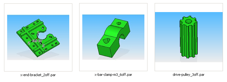
| drive-pulley_3off (alternative #1 #2 #3) | 1 | 1 | RP |
| x-bar-clamp-m3_6off | 4 | 4 | RP |
| x-end-bracket_2off | 1 | 1 | RP |
| m3-capx20 | 8 | 8 | Fastener |
| m3-nylock | 4 | 4 | Fastener |
| m3-washer | 12 | 12 | Fastener |
| 624-bearing | 4 | 4 | Bearing |
| m4-nylock | 4 | 4 | Fastener |
| m4-washer | 12 | 12 | Fastener |
| m4x16-cap | 4 | 4 | Fastener |
| m5-mudguard-washer | 4 | 4 | Fastener |
| stepper-motor-nema17-fl42sth47-1684A-01 | 1 | 1 | Motor |
Reprapped parts
Assembly
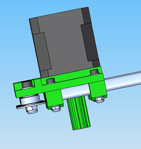
You might have a different looking X Motor Bracket, this is described here: [1]
Assembly is also compatible for NEMA 14 motors.
For all axis motors you'll need to file your own flats onto both sides of the drive shafts. There's a few essential tips for doing this:
- Put blue-tak/tape around the base of the drive shaft to prevent alloy filings getting dragged into the bearings (the motor's magnets will try to suck them in!)
- The flat should extend down the shaft to ~ 3mm from the face of the motor.
- Clamp the shaft, not the motor; carefully get it parallel to the vice by eye,
- The depth of the flat depends on your drive pulley hole profile, so have a good look before you do this.
- Ensure flat depths are even or you'll get a wobbly drive pulley.
- When filing, check frequently: if the flat shape is a rectangle, it's parallel to the axis; if it's a trapezium, it's not.
- The fit should be tight so that it won't come off on its own, but not too tight or you'll split the drive pulley.
- When pushing the drive pulley onto the motor shaft make sure the rear of the shaft is supported so that you can lightly tap the pulley with a hammer. Failure to support the back of the motor shaft will result in a broken motor.
- While you're tooled up you may as well do all the motors in one shot.
NOTE: Check the diameter of your stepper motor shaft first. Some motors have 5mm shafts while some have 3/16". The standard pulley above won't fit on a 5mm shaft (without lots of drilling and hammering, which usually leads to a wobbly, unusable pulley).
If you wish, you can leave the motor and toothed belt off at this stage and fit them later. (Maybe like me you are waiting for the postman...) If you do this, temporarily put four M3 washers and four ordinary M3 nuts (not nylocks) on the screws that will hold the motor.
If the bars are still covered in a film of oil to prevent rusting, thoroughly wipe this off now with a paper towel or similar. (Mineral oil can damage some plastics that RepRap uses to build parts.) It will be replaced with silicone grease later.
Fit the bars. Make sure the bars do not touch the bearings.
Final x-axis assembly
BOM
Total # of assemblies: 1
| Name | Qty/assembly | Total Qty | Type |
| x-motor-bracket | 1 | 1 | Assembly |
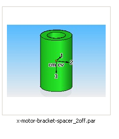
| x-motor-bracket-spacer_2off | 2 | 2 | RP |
| x-vert-bearing-360 | 1 | 1 | Assembly |
| x-vert-bearing-180 | 1 | 1 | Assembly |
| x-idler-bracket | 1 | 1 | Assembly |
| x-belt | 1 | 1 | Belt |
| x-carriage | 1 | 1 | Assembly |
| x-bar (495mm "X") | 2 | 2 | Bar |
Reprapped parts
Assembly
N.B. if you are using the alternative X motor bracket design, ensure you have the correct length x-bars before beginning assembly (they are shorter).
Lightly grease the rods with silicone grease. Silicone grease is inert as far as almost all plastics are concerned, and won't damage them. Slide the Motor bracket assembly onto the rods first, and tighten the clamps carefully. Add the other (motor spacers, 360 bearing, carriage, 180 bearing, idler bracket) assemblies in order, and tighten the clamps. Don’t tighten the belt until the x-axis is mounted on the main assembly.
The spacers are to get the dimensions roughly right on initial assembly. You may find, when you put the whole machine together, that they are a little short and that both their ends do not touch the neighboring parts. This is fine.
Links to users pictures and explanations
Back to Mendel mechanical construction root.
