Rostock mini
Release status: experimental
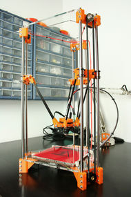
| Description | Rostock mini is a portable delta robot 3D printer based upon Johann's original.
|
| License | |
| Author | |
| Contributors | |
| Based-on | |
| Categories | |
| CAD Models | On Thingiverse
|
| External Link |
Contents
Overview
The Rostock mini is a delta 3D printer based on the modified design of the original Rostock created by Johann. The printer is designed to have a smaller build volume allowing for a smaller, more compact, portable, and desktop friendly version of the delta RepRap design. Using OpenSCAD, the parametric nature of the design files allows for print surfaces to be configured that range from as small as the default 152x152 mm (6x6 inches) all the way to 300x300 mm (12x12 inches) or more. Further, construction parameters such as the length of the drive belts, diagonal rods, and a laser cuttable frame as well as the firmware parameters such as diagonal rod length and delta radius are all automatically calculated based on the size of the specified print surface.
This design remains experimental and not fully tested. Updates will be made as and when possible.
Design Summary
The modifications to this design were driven by three factors:
- To experiment with the delta configuration in a printer with a smaller physical footprint
- To determine if the original Rostock design could be made more rigid (and thereby not need the heavy wood frame) if the vertical height was reduced considerably
- And finally to design a sleeker, parametric lower and upper frame suitable for laser cutting in wood or acrylic
While this design can be enlarged to fit an 8x8 or larger printbed, the vertical build height should be limited to maybe 8" to keep the frame rigid. Conversely, because of the torque needed to move the hotend platform, NEMA17 steppers are required making it difficult to scale any smaller than the Rostock mini default of a 6x6 printbed.
- Build volume: 152x152x192 mm (6x6x7.5 inches).
- Footprint: TBD.
- Print surface: 152x152 mm heated glass which never moves.
Designers note: While this design started as a way to explore really small delta-style printers, the need for the vertical towers to be greater than twice the height as the diagonal rods are long combined with the size of the effector platform and the need for motor torque in excess of 3kg-cm means that a build volume of 6"x6"x6" is about as small as this design can reasonably go. As most of the design efforts were spent on both making the design more parametric and designing a new upper and lower frame, the Rostock mini has failed in making a significantly smaller printer and has in effect simply become a more parametric version of the standard Rostock with a cool laser-cut frame. Even with that said, the Rostock mini is approximately 16" shorter and a few inches narrower than the original Rostock.
Development History
The Rostock mini is designed by Brian Evans.
Based on the innovative Rostock delta 3D printer designed by Johann.
Further contribution and parametric design by Greg Frost.
Development notes can be found at http://hardwired.cc/.
Original release: TBD.
Source Files
All source files can be found at Thingiverse.
The design files are licensed under the GPL open license.
Bill of Materials
The bill of materials is still being ironed out but here's a stab at it.
Printed Parts
- Motor end qty3
- Idler end qty3
- Carriage qty3
- U-joints qty12
- Jaws qty12 (or Rods qty6)
- Platform qty1
- Hotend mount qty1
- Fan mount qty1
- Extruder qty1
Laser Cut Parts
- Lower frame qty1 - 6mm acrylic
- Upper frame qty1 - 6mm acrylic
- Printbed insulator qty1 - 1/8" cork
- NEMA17 gaskets qty3 - 1/8" cork
Electro-mechanical
- NEMA17s qty3 - 4.7kg-cm or more
- 608ZZ ball bearings qty6
- LM8UU linear bearings qty6
- 36tooth GT2 timing pulley qty3 - 40 tooth will also work
- GT2 timing belt qty3 - 2.0mm pitch 976mm length or to configuration
- Subminiature switch qty3 - Omron SS-5 or similar with no lever
- Sanguinololu controller qt1 - or similar
- 6x6 heated printbed qty1
- MakerGear groovemount hotend qty1
- 40mm cooling fan qty1
- N-channel MOSFET qty1 - IRF540 or similar
Hardware
- M2.5x10 qty6
- M3x10 qty7 - flathead
- M3x12 qty76
- M3x16 qty12
- M3 fender washer qty30
- M3 washer qty40
- M3 nuts qty56
- M4x16 qty20
- M4 washer qty20
- M4 nuts qty4
- M8x30 qty3
- M8 washer qty6
- M8 nuts qty3
- 8mm precision ground rod qty6 - 492mm length or as configured
- 0.188" OD rigid carbon fiber tube qty6 - 166mm length or as configured
- 6"x6" 3/16" thick borosilicate glass
Assembly Build Notes
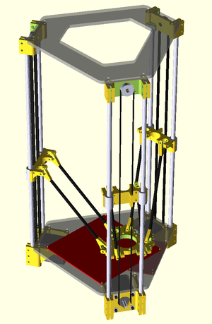
To see how the Rostock mini is assembled, refer to the OpenSCAD file, Rostock_mini.SCAD, pictured above and available in the source files. Assembly is as follows:
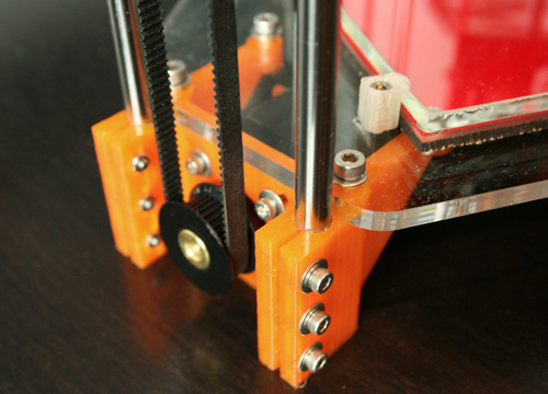
- Begin by constructing each of the three towers, starting with the motor end, then the idler end, followed by the carriage, and then putting it all together to complete the tower.
- Complete the frame by attaching the motor ends of each tower to the lower frame before attaching the upper frame to the idler ends.
- Assemble the end effector platform, assembling and attaching the diagonal rods as you go.
- Attach the ends of each diagonal rod to the carriages on each tower to complete the mechanical assembly.
- Finally, install the electronics, mount the extruder, and complete the wiring.
What follows are abbreviated notes for each of these assembly steps.
Motor End
- Begin the motor end assembly by taping the four mounting holes for the lower frame with an M4 tap.
- Drill each of the six M3 holes with a 7/64 or #35 drill bit.
- Insert six M3x12 screws using fender washers and nuts but do not tighten.
- Insert 8mm smooth rods into the top of the motor mount until just shy of the bottom of the opening.
- Once both rods are adjusted to the same length, tighten each M3 screw to secure the smooth rods.
- Mount the NEMA17 motor using four M3x10 screws with washers or M3x12 screws and washers with a cork gasket.
- Attach a 36-tooth timing pulley to the motor shaft.
Idler End
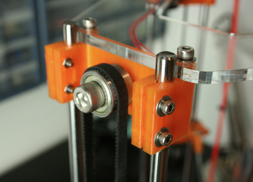
- Tap the two mounting holes for the upper frame with an M4 tap
- Drill each of the four M3 holes with a 7/64 or #35 drill bit
- Insert four M3x12 screws using fender washers and nuts but do not tighten
- Insert M8x30 screw through two 608ZZ bearings and one M8 washer and thread through the idler end until tight
- Tighten idler on the inside with a M8 washer and nut using a wrench and allen key
Note: The M8x30 screw should be very tight in the idler end.
Carriage
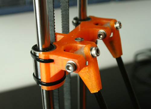
- Cut out the supports in the timing belt retainer
- Tap the endstop screw hole with an M3 tap
- Thread an M3x10 flat or button head screw for endstop adjustment
- Drill each of the four M3 holes for the u-joints with a 3/32 or #40 drill bit
- Set four M3 nuts on the inside of each u-joint using a soldering iron to heat the nut to make it flush with the opening, shown here
- Insert four M3x12 screws using fender washers but do not tighten and leave the u-joint open
- Drill each of the four M3 holes in two u-joints with a 3/32 or #40 drill bit
- Lubricate the holes and bearing surfaces of each u-joint with PTFE grease or 3-in-One motor oil
- Insert both u-joints into the carriage and tighten the four M3 screws
- Insert two LM8UU linear bearings and secure with four 7/8"x4-1/8" zip ties
Note: The u-joints should be tight but still move freely. These will wear in with time.
Frame
- Complete the towers by sliding the carriage on each pair of 8mm smooth rods
- Slide an idler end on top of each pair of rods making sure to align the top and bottom of the tower keeping the rods parallel
- Once each tower is assembled but before tightening the idler end, stretch a GT2 timing belt over the pulley, between the belt holder on the carriage, and over the idler
- Pulley upwards on the idler to tension the timing pulley, tighten all four M3 screws to finish the tower.
- Once the towers are complete, attach the lower frame to the motor ends of each tower using M4x16 screws and washers; three on each of the front towers and four on the rear tower
- Attach the upper frame to the idler ends of each tower using two M4x16 screws and washers on each tower
Platform
- Drill each of the six M4 holes for the hot end with a 5/32 or #22 drill bit
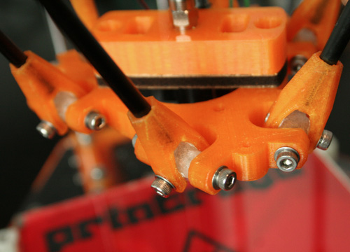
- As with the carriage, drill each of the twelve M3 holes for the u-joints with a 3/32 or #40 drill bit
- Set twelve M3 nuts on the inside of each u-joint using a soldering iron to heat the nut to make it flush with the opening, shown here
- Insert twelve M3x12 screws using fender washers but do not tighten and leave the u-joint open
- Drill each of the twelve M3 holes in six u-joints with a 3/32 or #40 drill bit
- Lubricate the holes and bearing surfaces of each u-joint with PTFE grease or 3-in-One motor oil
- Insert all six u-joints into the platform and tighten the twelve M3 screws
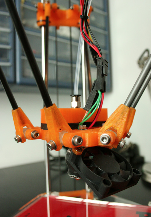
- Attach 40mm fan to fan mount using two M3x12 flat-head screws and nuts, then attach mount to platform with two M3x12 socket-head screws, washers, and nuts
Diagonal Rods
- Cut six pieces of .188" OD rigid carbon fiber tube to lengths of 20mm short of the calculated diagonal rod length
- For this build, the diagonal rod length was calculated to be 186mm so the rods were cut to 166mm in length
- Use cyanoacrylate (super glue) or epoxy to glue a diagonal rod end (jaw) to each end of the carbon fiber tube
- Be sure to keep the rod ends flat to a table and all at the same distance
- Once the glue is dry, drill each of the twenty-four M3 holes for the u-joints with a 3/32 or #40 drill bit
- Attach each diagonal rod to each u-joint on platform using an M3x16 screw and washer
- Nuts were not used in this build because of clearance although M3x20 button-head screws and locknuts could be used instead
- Finally, attach the other end of the diagonal rods to the carriage u-joints, connect platform to carriages
Extruder
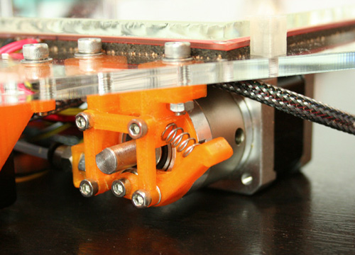
- Clockwork extruder on Thingiverse
- TO DO: Needs further testing and documentation
Hotend
- TO DO: Needs further testing and documentation
Endstops
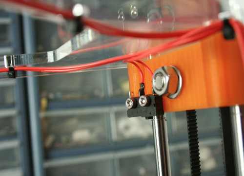
- Solder two 26-22AWG wires to each switch, with lengths sufficiently longer than the vertical smooth rods
- Secure each endstop switch to the inside of each idler end using two M2.5x10 screws in the orientation shown
- Without M2.5 screws the switch mounting holes need to be drilled with a 7/64 or #35 drill bit and each hole in the idler tapped to M3 and secured with M3x12 screws
Note: I prefer to connect the endstop wires to the COM and NO pins on the switch. This either needs to be accounted for in firmware or wired instead to COM and NC.
Wiring
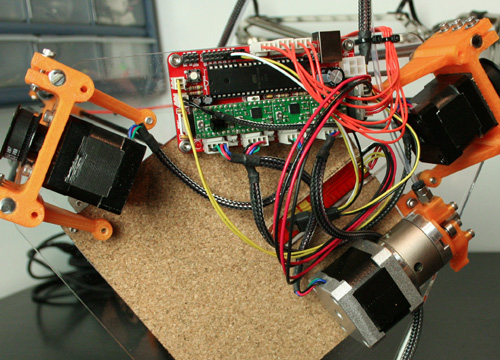
- The default controller for the Rostock mini is the Sanguinololu with an ATmega1284P micro
- With the printer right side up, the motor and endstop for the front left tower are connected to X, front right to Y, and rear to Z
- TO DO: Platform cooling fan connected to external MOSFET - needs documentation
Note: This image shows NEMA14 stepper motors rather than 17 but they don't work - not enough torque. Will update once 17s are installed.
Bootloader and Firmware
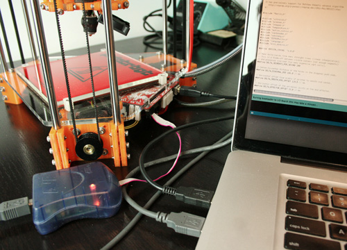
The Rostock mini uses the Sanguinololu controller with an upgraded 1284P using the Azteeg X1 bootloader and a modified firmware taken from Johann's fork of the Marlin firmware. More details on the installation and configuration can be found here.
Commissioning
- TO DO
Customizing
The parametric nature of the Rostock mini allows for quite a bit of customization to suit the build volume and mounting options of your choice. Here's how to customize the design. TO DO
Future Development
- Traxxas 5347 u-joints
- Reuleaux triangle frame
- Round polyimide heatbed - Jay did this: Jay's adjustable round print bed.
- Dog-style belt clamp on carriages - In progress on Thingiverse (part number 40502 )
