Raspberry Pi based 4 axis controller
Posted by mrwolfe
|
Raspberry Pi based 4 axis controller September 14, 2015 02:27AM |
Registered: 8 years ago Posts: 15 |
Hi All.
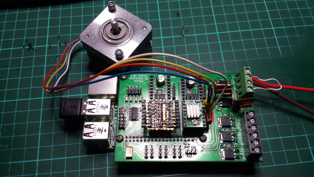
I'm currently working on a controller board for the Raspberry Pi. I have a prototype built (see the pic) and I'm in the process of checking it out, although the software is kicking my butt a bit. I'm using the BCM2835 library to interface with the GPIO, and it works, but it really needs to run on xenomai or some other RT Kernel.
I'm hoping to get it to the point where I can put it up on kickstarter. Projected price is less than $50
Anyway, the specs are:
Motor control:
4 channels, using A4988 or DRV8825 stepstick drivers. Motor power is separate, and can be anything from 12V to 45V.
Limit switches:
6 limit inputs with 3.3v supplies (Note that the Pi cannot take standard 5V TTL signals, although this doesn't really matter for the limit switches)
Thermistors:
4 thermistor inputs and 4 auxilliary analog input channels (for whatever. They were there, so I included them).
Discrete outputs:
3 Discretes to control the heater, fan and bed. Still pondering whether to make these 12V or 12V/24V. Max currernt of the FET drivers is 35A, but the PCB is limited to less than this.
Onboard 3.3v and 5V:
The board powers the Pi from the 12v input.
Size:
Just a little bigger than the Pi: 100mm x 70mm x 20mm high (with the stepsticks installed)
There is also a spare SPI port for future expansion (add-on motor drivers and the like)
I'm also toying with the idea of adding a PIC or Atmel chip to handle the timing critical stuff, but I'd like to see how the Pi goes with an EMC style implimentation.
Tony
Edited 1 time(s). Last edit at 09/14/2015 02:28AM by mrwolfe.
|
Re: Raspberry Pi based 4 axis controller September 14, 2015 04:50AM |
Registered: 9 years ago Posts: 978 |
Just as a data point, I wouldn't be interested in anything with only 4 steppers. Maybe if you already had an expansion board available right from the start to provide another 2-3.
Are the "limit switch" inputs compatible with active sensors (e.g. optical or Hall-effect?)
But mostly I'd want to know beforehand how you were going to solve the RT control issue.
What software would you implement? A variant of Marlin? Or something different?
Are the "limit switch" inputs compatible with active sensors (e.g. optical or Hall-effect?)
But mostly I'd want to know beforehand how you were going to solve the RT control issue.
What software would you implement? A variant of Marlin? Or something different?
|
Re: Raspberry Pi based 4 axis controller September 14, 2015 10:10AM |
Registered: 9 years ago Posts: 517 |
For the end stop voltage difference, add a mosfet to each input. That would allow higher voltage to be used. Might set it up in a way the user could use a jumper for anything over 3.3v.
4 steppers is not enough these days. Optional unpopulated space for at least two more steppers would be good. Also providing digitally controlled reference voltage for the stepper sticks would be good. I have seen one stick available that has an input for an external reference voltage.
If there are more free pins available, you should add more discrete outputs.
|
Re: Raspberry Pi based 4 axis controller September 17, 2015 02:13PM |
Registered: 9 years ago Posts: 198 |
|
Re: Raspberry Pi based 4 axis controller September 25, 2015 03:08AM |
Registered: 8 years ago Posts: 15 |
Hi.
Yep it is expandable via the SPI port. I have an expansion board in the pipeline that will probably have an Atmel or Pic MCU. The only reason it only has 4 drivers is that I was trying to keep it small, and I needed 6 GPIO pins for limits. The limit inputs are compatible with mechanical and opto switches, or any sensor type that can run from 3.3v. The only caveat is that they must be either powered from the Pilolu board or a supply no greater than 3.3v to the GPIO pin.
I'm thinking that Marlin would be a good place to start, but it would be split into two parts. The stepgen would be handled by a kernel mode driver module (possibly spinlock, but I'm not at all sure about that), with the G-Code decoder running in user space. The two would be connected by a buffer. Having not had a close look at Marlin, I'm not sure how the two functions are handled, but I'm thinking that there would need to be an intermediate code to control the stepgen.
The main idea was to try to keep it small and still have the advantages of having WiFi and Bluetooth capability. A Raspberry Pi based board has already been done, but it's pretty big.
Edited 1 time(s). Last edit at 09/25/2015 03:28AM by mrwolfe.
Yep it is expandable via the SPI port. I have an expansion board in the pipeline that will probably have an Atmel or Pic MCU. The only reason it only has 4 drivers is that I was trying to keep it small, and I needed 6 GPIO pins for limits. The limit inputs are compatible with mechanical and opto switches, or any sensor type that can run from 3.3v. The only caveat is that they must be either powered from the Pilolu board or a supply no greater than 3.3v to the GPIO pin.
I'm thinking that Marlin would be a good place to start, but it would be split into two parts. The stepgen would be handled by a kernel mode driver module (possibly spinlock, but I'm not at all sure about that), with the G-Code decoder running in user space. The two would be connected by a buffer. Having not had a close look at Marlin, I'm not sure how the two functions are handled, but I'm thinking that there would need to be an intermediate code to control the stepgen.
The main idea was to try to keep it small and still have the advantages of having WiFi and Bluetooth capability. A Raspberry Pi based board has already been done, but it's pretty big.
Quote
frankvdh
Just as a data point, I wouldn't be interested in anything with only 4 steppers. Maybe if you already had an expansion board available right from the start to provide another 2-3.
Are the "limit switch" inputs compatible with active sensors (e.g. optical or Hall-effect?)
But mostly I'd want to know beforehand how you were going to solve the RT control issue.
What software would you implement? A variant of Marlin? Or something different?
Edited 1 time(s). Last edit at 09/25/2015 03:28AM by mrwolfe.
|
Re: Raspberry Pi based 4 axis controller September 25, 2015 03:09AM |
Registered: 8 years ago Posts: 15 |
|
Re: Raspberry Pi based 4 axis controller September 25, 2015 03:25AM |
Registered: 8 years ago Posts: 15 |
I guess I'm just feeling around at the moment to find out what people think. Adding extra circuitry on the end stop inputs is a possibility, but the board will have to get bigger. I've deliberately used 0805 and larger sized components because they can be hand soldered. If I go full commercial, the components will get smaller but you won't be able to assemble it at home.
Reference voltage? Standard stepsticks have a pot to set the motor current. Neither motors nor drivers get hot under normal circumstances, so I'm not sure why anyone would want to control that dynamically.
Extra pins are an issue because the GPIO only has 21 pins plus SPI (which can be 5 GPIO pins or SPI but not both) and ID (which can't be used for anything except the device ID rom). Extra dIscretes can be added via an expansion board. Again, everything can be added but the size and cost goes up.
I've just remembered the OTHER reason that I kept the board size down. I cut the board down and did quite a bit of squeezing because if it gets any bigger it goes into the next size range and gets more expensive.
Quote
ElmoC
For the end stop voltage difference, add a mosfet to each input. That would allow higher voltage to be used. Might set it up in a way the user could use a jumper for anything over 3.3v.
4 steppers is not enough these days. Optional unpopulated space for at least two more steppers would be good. Also providing digitally controlled reference voltage for the stepper sticks would be good. I have seen one stick available that has an input for an external reference voltage.
If there are more free pins available, you should add more discrete outputs.
|
Re: Raspberry Pi based 4 axis controller September 25, 2015 03:36AM |
Registered: 8 years ago Posts: 15 |
|
Re: Raspberry Pi based 4 axis controller September 25, 2015 06:31PM |
Registered: 9 years ago Posts: 74 |
|
Re: Raspberry Pi based 4 axis controller September 27, 2015 02:25AM |
Registered: 8 years ago Posts: 15 |
Not at all sure what happened to Photon Elephant. They certainly seem to have gone to ground though. Havent seen anything about them violating anyone's IP. I'm pretty sure that I'm not violating anyone's patent, the Pi GPIO and all is open source, as are the concept and the circuitry of RAMPS, Melzi etc. I was thinking of calling it the "Pilolu" (Raspberry pi with pololu drivers), maybe I should rethink that.
Quote
zerodameaon
Check around to make sure you are not going to violate any patents or anything like that. Photon Elephant eluded to possibly violating something with their PI based board before they vanished into thin air with everyone's money.
|
Re: Raspberry Pi based 4 axis controller September 27, 2015 02:23PM |
Registered: 9 years ago Posts: 74 |
The name might work. The reason I brought it up was simply because I would like to see something like this come through. If it is reliable it would be good for a side printer you don't mess with so you can print parts for the one you are always messing with and breaking. Not saying this will limit you to just a reliable printer but that would be the selling point for me.
|
Re: Raspberry Pi based 4 axis controller September 28, 2015 04:50AM |
Registered: 9 years ago Posts: 978 |
Quote
mrwolfe
It has an SPI port on it which can be used for expansion.
Yeah, but I don't have the knowledge and skills to translate that into some working stepper drivers. And lots of other things to do, so I don't want to develop this. Hence, your device would be much more interesting if that expansion board could be bought with it.
|
Re: Raspberry Pi based 4 axis controller October 03, 2015 10:40AM |
Registered: 8 years ago Posts: 2 |
Hi,
I'm toying with the idea of building a 3D printer that has a graphical display for more options on what to display, networking to avoid the hassle with usb sticks or sd cards, live video so I can watch the printing while I'm cooking in the kitchen and maybe include the slicer. A Raspberry Pi might provide all that.
How many pins do you use so far? I see the need for at least:
4 X Axis: X_STEP_PIN X_DIR_PIN X_ENABLE_PIN X_MIN_PIN
4 Y Axis: Y_STEP_PIN Y_DIR_PIN Y_ENABLE_PIN Y_MIN_PIN
4 Z Axis: Z_STEP_PIN Z_DIR_PIN Z_ENABLE_PIN Z_MIN_PIN
3 E Axis: E_STEP_PIN E_DIR_PIN E_ENABLE_PIN
2 Extruder: HEATER_PIN TEMP_PIN (analog)
=
17 Pins
That would leave 4 + SPI or 9 pins free. If all ENABLE pins are connected together that would save 3 pins. Adding MAX_PIN for each axis would use 3 more pins.
With 4 pins there isn't enough space for a second extruder. Unless some pins could be reused or multiplexed. Ideas:
Support for 2 extruders and heated plate with the extruders multiplexed by a tristate pin would come to a total of 21 pins by my count.
And how do you handle the analog TEMP_PINs? Unlike an Arduino the Raspberry Pi has only digital inputs. I assume you have some 8 channel AD converter chip?
The prices I have for etching boards have 50mm x 50mm and 100mm x 100mm price classes (50mm x 100mm costs the same). Your board is 100mm x 70mm. So there would be room for an extra 30mm width at no price.
I might be interested in writing a linux driver for the board or go one step lower and work bare-metal. Obviously it would help to have a board to play with. Do you have a spare board or could you provide schematics, layouts and parts list? Will your board be GPL like the RAMPS?
As for the $50 price have you seen [www.banggood.com] ? Would be cheaper to connect that to a Raspberry Pi via USB and use that as display + network controller and slicer. But half the fun is in building this yourself.
I'm toying with the idea of building a 3D printer that has a graphical display for more options on what to display, networking to avoid the hassle with usb sticks or sd cards, live video so I can watch the printing while I'm cooking in the kitchen and maybe include the slicer. A Raspberry Pi might provide all that.
Quote
mrwolfe
Extra pins are an issue because the GPIO only has 21 pins plus SPI (which can be 5 GPIO pins or SPI but not both) and ID (which can't be used for anything except the device ID rom). Extra dIscretes can be added via an expansion board. Again, everything can be added but the size and cost goes up.
How many pins do you use so far? I see the need for at least:
4 X Axis: X_STEP_PIN X_DIR_PIN X_ENABLE_PIN X_MIN_PIN
4 Y Axis: Y_STEP_PIN Y_DIR_PIN Y_ENABLE_PIN Y_MIN_PIN
4 Z Axis: Z_STEP_PIN Z_DIR_PIN Z_ENABLE_PIN Z_MIN_PIN
3 E Axis: E_STEP_PIN E_DIR_PIN E_ENABLE_PIN
2 Extruder: HEATER_PIN TEMP_PIN (analog)
=
17 Pins
That would leave 4 + SPI or 9 pins free. If all ENABLE pins are connected together that would save 3 pins. Adding MAX_PIN for each axis would use 3 more pins.
With 4 pins there isn't enough space for a second extruder. Unless some pins could be reused or multiplexed. Ideas:
- Only one extruder is used at a time
shared E_STEP_PIN and E_DIR_PIN and tristate E_ENABLE_PIN (0 = left, 1 = right, float = off) - Z Axis movement is done only inbetween layers (when extruders aren't used)
shared E/Z_STEP_PIN and E/Z_DIR_PIN, 2 pins E1/E2/Z select
Support for 2 extruders and heated plate with the extruders multiplexed by a tristate pin would come to a total of 21 pins by my count.
And how do you handle the analog TEMP_PINs? Unlike an Arduino the Raspberry Pi has only digital inputs. I assume you have some 8 channel AD converter chip?
Quote
mrwolfe
I've just remembered the OTHER reason that I kept the board size down. I cut the board down and did quite a bit of squeezing because if it gets any bigger it goes into the next size range and gets more expensive.
The prices I have for etching boards have 50mm x 50mm and 100mm x 100mm price classes (50mm x 100mm costs the same). Your board is 100mm x 70mm. So there would be room for an extra 30mm width at no price.
Quote
mrwolfe
Oh, BTW, I could really use some help with the software. Anyone out there have any experience writing kernel mode drivers in a realtime linux environment?
I might be interested in writing a linux driver for the board or go one step lower and work bare-metal. Obviously it would help to have a board to play with. Do you have a spare board or could you provide schematics, layouts and parts list? Will your board be GPL like the RAMPS?
As for the $50 price have you seen [www.banggood.com] ? Would be cheaper to connect that to a Raspberry Pi via USB and use that as display + network controller and slicer. But half the fun is in building this yourself.
|
Re: Raspberry Pi based 4 axis controller October 03, 2015 08:21PM |
Registered: 8 years ago Posts: 15 |
Quote
mrvn
Hi,
I'm toying with the idea of building a 3D printer that has a graphical display for more options on what to display, networking to avoid the hassle with usb sticks or sd cards, live video so I can watch the printing while I'm cooking in the kitchen and maybe include the slicer. A Raspberry Pi might provide all that.
The Pi has the capacity to do USB, LAN, HDMI, camera, LCD and web interface, as well as WiFi, and Bluetooth with additional hardware, but from experience it's very slow for slicing.
Quote
mrvn
Quote
mrwolfe
Extra pins are an issue because the GPIO only has 21 pins plus SPI (which can be 5 GPIO pins or SPI but not both) and ID (which can't be used for anything except the device ID rom). Extra dIscretes can be added via an expansion board. Again, everything can be added but the size and cost goes up.
How many pins do you use so far? I see the need for at least:
4 X Axis: X_STEP_PIN X_DIR_PIN X_ENABLE_PIN X_MIN_PIN
4 Y Axis: Y_STEP_PIN Y_DIR_PIN Y_ENABLE_PIN Y_MIN_PIN
4 Z Axis: Z_STEP_PIN Z_DIR_PIN Z_ENABLE_PIN Z_MIN_PIN
3 E Axis: E_STEP_PIN E_DIR_PIN E_ENABLE_PIN
2 Extruder: HEATER_PIN TEMP_PIN (analog)
=
17 Pins
That would leave 4 + SPI or 9 pins free. If all ENABLE pins are connected together that would save 3 pins. Adding MAX_PIN for each axis would use 3 more pins.
The current list is:
X, Y, Z, E motors: 8 pins plus 1 for enable (my initial design had 3 pins per motor)
Bed, Fan, Extruder : 3 pins
Endstops: 6 pins
Interrupt Tick: 1 pin
Spare: 2 pins (so, yes, a 5th motor channel is possible)
Not sure whether the interrupt tick will be necessary. The idea is to use a 10ms (or whatever) pulse generated by an on board circuit as an RTC interrupt (The Pi has no RTC). It may be possible to impliment this in software, expecially for a bare metal implimentation which could dedicate one of the system timers to it.
Quote
mrvn
With 4 pins there isn't enough space for a second extruder. Unless some pins could be reused or multiplexed. Ideas:
- Only one extruder is used at a time
shared E_STEP_PIN and E_DIR_PIN and tristate E_ENABLE_PIN (0 = left, 1 = right, float = off)- Z Axis movement is done only inbetween layers (when extruders aren't used)
shared E/Z_STEP_PIN and E/Z_DIR_PIN, 2 pins E1/E2/Z select
Not bad ideas. There are 2 spare pins ATM that could be used as select lines. Taking this idea to its logical conclusion, you could multiplex all of the motor control lines e.g Common Step, Direction, plus 7 enable lines for 7 motor channels. Only problem is that only one motor can be driven at a time. Another possibility is to have seperate X and Y channels with all the others multiplexed i.e
XDir, XStep, XYEn
YDir, YStep
CDir, CStep, EN1, EN2, EN3, EN4 (assuming the 2 spares are used as well)
Of course, squeezing all of this into a small space is challenging.
I have also started thinking about a version that uses SPI to talk to all of the drivers. That would free up a lot of GPIO pins, allow an almost unlimited number of output channels and possibly make the whole thing simpler - everyhting is done via SPI except the limit switches.
Quote
mrvn
Support for 2 extruders and heated plate with the extruders multiplexed by a tristate pin would come to a total of 21 pins by my count.
And how do you handle the analog TEMP_PINs? Unlike an Arduino the Raspberry Pi has only digital inputs. I assume you have some 8 channel AD converter chip?
Yep, I have am MCP3008 connected to the SPI port. Because it's an 8 channel A/D (I COULD have used the 4 channel MCP3004, they are about the same price) I have 4 thermocouple channels and 4 extra analog input channels. The required sample rate is not high, and the extra channels add a bit of versatility.
Quote
mrvn
Quote
mrwolfe
I've just remembered the OTHER reason that I kept the board size down. I cut the board down and did quite a bit of squeezing because if it gets any bigger it goes into the next size range and gets more expensive.
The prices I have for etching boards have 50mm x 50mm and 100mm x 100mm price classes (50mm x 100mm costs the same). Your board is 100mm x 70mm. So there would be room for an extra 30mm width at no price.
Seeed studio, I presume?

Quote
mrvn
Quote
mrwolfe
Oh, BTW, I could really use some help with the software. Anyone out there have any experience writing kernel mode drivers in a realtime linux environment?
I might be interested in writing a linux driver for the board or go one step lower and work bare-metal. Obviously it would help to have a board to play with. Do you have a spare board or could you provide schematics, layouts and parts list? Will your board be GPL like the RAMPS?
I'm planning to go mostly GPL, although I'm also hoping to make a little money from it as I'm currently unemployed (It's a problem when you're an Aerospace engineer in a city where there is no Aerospace industry left), I have some prototype boards and I can sent you one if you're willing to help.
At this stage, I think a RT kernel module to handle the stepgen and I/O would be the thing to aim for. Once the kernelspace side is in place the userspace side is open for all to play with. I'm thinking along the lines of a kernel module with the highest priority that just takes step commands from a buffer and outputs them to the port with minimal translation. The conversion from GCode to step commands could be done in userspace (with RT priority) as long as the buffer is big enough.
Quote
mrvn
As for the $50 price have you seen [www.banggood.com] ? Would be cheaper to connect that to a Raspberry Pi via USB and use that as display + network controller and slicer. But half the fun is in building this yourself.
Yes, RAMPS stuff is getting cheaper all the time. I was looking at Photon Elephant a while ago, but they seem to have dissapeared into a hole somewhere. Photon Elephant was also WAAAAY too expensive, as well as being big. One of the reasons for going the way I have is to keep the whole thing in a neat, compact package that can be used as a network connected 3D printer, a robot, or anything else that you can think of.
Connecting a RAMPS to a Pi via USB is certainly cheap (already done that), but I kind of like the idea of a single unit instead of having cables all over the place. As for the price, I'm pretty confident I can get it down to about the same as that RAMPS kit, but I'll need to do it in volume to get there.
|
Re: Raspberry Pi based 4 axis controller October 04, 2015 06:38AM |
Registered: 8 years ago Posts: 2 |
Quote
mrwolfe
Not bad ideas. There are 2 spare pins ATM that could be used as select lines. Taking this idea to its logical conclusion, you could multiplex all of the motor control lines e.g Common Step, Direction, plus 7 enable lines for 7 motor channels. Only problem is that only one motor can be driven at a time. Another possibility is to have seperate X and Y channels with all the others multiplexed ...
I would leave the X/Y motors seperate for sure. Diagonal lines are verry common and then you want to step both motors at the same time exactly. Also for every other non axis line you have to step each motor in exact ratios to each other. If you have to step them one after each other then you generate a whobble whenever the two motors need to be stepped to close together. So I would only multiplex motors that won't be used together at the same time.
I was also thinking of using an actual multiplexer, not seperate enable lines. So you would have one signal line and then log(N) address lines. So 3 lines would give you 4 motors, 4 lines 8 motors, 5 lines 16 motors and so on. The signal line can be GND or Vcc if you leave one output of the multiplexer free. That way 2 lines would give you controll of 3 motors as I previously used.
Edited 1 time(s). Last edit at 10/04/2015 06:44AM by mrvn.
|
Re: Raspberry Pi based 4 axis controller October 09, 2015 03:40AM |
Registered: 8 years ago Posts: 15 |
The only thing is that once you start adding extra glue logic there are better ways to go such as running all the outputs via SPI. That way all the GPIO pins can be used as inputs. For that matter, the inputs can also be done using SPI, which gets away from the voltage sensitivity of the GPIO pins.
For the moment, I think there is some value to be extracted from using my existing layout to get the RT kernel module stuff sorted out. That will give anyone who wants to do something similar a starting point.
For the moment, I think there is some value to be extracted from using my existing layout to get the RT kernel module stuff sorted out. That will give anyone who wants to do something similar a starting point.
Quote
mrvn
I was also thinking of using an actual multiplexer, not seperate enable lines. So you would have one signal line and then log(N) address lines. So 3 lines would give you 4 motors, 4 lines 8 motors, 5 lines 16 motors and so on. The signal line can be GND or Vcc if you leave one output of the multiplexer free. That way 2 lines would give you controll of 3 motors as I previously used.
|
Re: Raspberry Pi based 4 axis controller October 09, 2015 03:57AM |
Registered: 9 years ago Posts: 978 |
|
Re: Raspberry Pi based 4 axis controller October 09, 2015 05:21PM |
Registered: 10 years ago Posts: 14,672 |
Quote
mrwolfe
Connecting a RAMPS to a Pi via USB is certainly cheap (already done that), but I kind of like the idea of a single unit instead of having cables all over the place. As for the price, I'm pretty confident I can get it down to about the same as that RAMPS kit, but I'll need to do it in volume to get there.
I see two problems with a RAMPS + Pi solution. One is that Arduino Mega/RAMPS is not adequate to drive a delta printer well. The other is that I have recently seen two different users complain that their Octoprint on RPi does not supply data over the USB port to their Arduino Mega/RAMPS printers fast enough to print at full speed. I suspect the issue is that the Pi was also running a webcam, and the lack of hardware flow control in the serial part of the USB-over-serial link on the Mega means that the Pi has to wait for an "OK" response before it knows it is safe to send more data - which leads to Linux descheduling Octoprint in favour of other tasks such as servicing the webcam. So if you want to couple a Pi with another processor to do the hard real time stuff, use a faster processor, and either make sure it has a native USB port or use some other protocol such as SPI to connect them.
There are other solutions to providing a network interface to a 3D printer that don't involve using anything as powerful as a Pi or a general purpose O/S such as Linux, but they can't handle webcams, or local slicing.
I have wondered whether it would be possible to hack the Linux kernel to use only 3 cores of a quad core chip, leaving the 4th core free for real time tasks. I also heard of a chip recently that combines quad cores for running Linux etc. with a lower-spec ARM core for running real time tasks. That sounds like a good combination to me.
Large delta printer [miscsolutions.wordpress.com], E3D tool changer, Robotdigg SCARA printer, Crane Quad and Ormerod
Disclosure: I design Duet electronics and work on RepRapFirmware, [duet3d.com].
|
Re: Raspberry Pi based 4 axis controller October 10, 2015 05:02AM |
Admin Registered: 16 years ago Posts: 13,889 |
... I'm developing a 'high-speed' application with an UDOO (linux quad-core with ArduinoDue onboard) as 'master' and two Dues as 'slaves' for motion control and laser-syncing.
With reading data from SD and setting the laser-power over an analog port I'm getting something like 90kHz 'pixel-clock' ... without the analog output this will be more something like 400kHz.
With a BeagleBone-based laser controller I'll get something like 500kHz normal pixel-clock to 2MHz pwm-speeds for simple set frequenzies ...
Viktor
--------
Aufruf zum Projekt "Müll-freie Meere" - [reprap.org] -- Deutsche Facebook-Gruppe - [www.facebook.com]
Call for the project "garbage-free seas" - [reprap.org]
|
Re: Raspberry Pi based 4 axis controller October 10, 2015 10:12AM |
Registered: 10 years ago Posts: 14,672 |
Quote
VDX
With reading data from SD and setting the laser-power over an analog port I'm getting something like 90kHz 'pixel-clock' ... without the analog output this will be more something like 400kHz.
What analog output mechanism are you using? Sounds like it is seriously sub-optimal.
Large delta printer [miscsolutions.wordpress.com], E3D tool changer, Robotdigg SCARA printer, Crane Quad and Ormerod
Disclosure: I design Duet electronics and work on RepRapFirmware, [duet3d.com].
|
Re: Raspberry Pi based 4 axis controller October 10, 2015 02:14PM |
Admin Registered: 16 years ago Posts: 13,889 |
... sure! - this was a simple first test with the Arduino IDE and "analogWrite()", so could be highly optimized with a more hardware specific code 
here is the used test-code - some of the functionality is only there to simulate load, the serial output is for some sort of logging while testing:
Viktor
--------
Aufruf zum Projekt "Müll-freie Meere" - [reprap.org] -- Deutsche Facebook-Gruppe - [www.facebook.com]
Call for the project "garbage-free seas" - [reprap.org]
here is the used test-code - some of the functionality is only there to simulate load, the serial output is for some sort of logging while testing:
  myFile = SD.open("datalog.txt");
  if (myFile) {
    Serial.println("datalog.txt:");

    // read from the file until there's nothing else in it:
    char SDbyte = 0;
    starttime = millis();
    while (myFile.available()) {
      linenumber += 1;
      SDbyte = myFile.read();
      if (buttonPin){
        //analogWrite(analogOutPin, SDbyte);
        analogWrite(A0, SDbyte);
        //digitalWrite(ledPin, HIGH);
        //digitalWrite(ledPin, LOW);
        //analogWrite(A1, 255);
        //analogWrite(A1, 0);
        if (SDbyte<255){
          ttime = millis() - starttime;
          Serial.print(linenumber);
          Serial.print(": ");
          Serial.print(SDbyte, DEC); //HEX);
          Serial.print(" - ");
          Serial.print(ttime/1000);
          Serial.write("\n");
          }
       }
    }
    // close the file:
    myFile.close();
Viktor
--------
Aufruf zum Projekt "Müll-freie Meere" - [reprap.org] -- Deutsche Facebook-Gruppe - [www.facebook.com]
Call for the project "garbage-free seas" - [reprap.org]
|
Re: Raspberry Pi based 4 axis controller October 10, 2015 06:59PM |
Admin Registered: 16 years ago Posts: 13,889 |
... before you ask - the serial output will start after some ten millions of SD-reads with a 255 byte-code (it's reading a gigantic image-file), so the first serial log will print a linenumber and the time from start to first found pixel, so I can calculate the precise time needed for a single SD-read- and analogWrite-sequence ...
Viktor
--------
Aufruf zum Projekt "Müll-freie Meere" - [reprap.org] -- Deutsche Facebook-Gruppe - [www.facebook.com]
Call for the project "garbage-free seas" - [reprap.org]
Viktor
--------
Aufruf zum Projekt "Müll-freie Meere" - [reprap.org] -- Deutsche Facebook-Gruppe - [www.facebook.com]
Call for the project "garbage-free seas" - [reprap.org]
|
Re: Raspberry Pi based 4 axis controller October 12, 2015 06:21AM |
Registered: 8 years ago Posts: 31 |
[wiki.linuxcnc.org] What about linuxcnc?
|
Re: Raspberry Pi based 4 axis controller October 12, 2015 11:39PM |
Registered: 8 years ago Posts: 15 |
Quote
frankvdh
There's a KickStarter project called Replicape for a 3D printer controller based around a BeagleBone Black, which apparently has some extra hardware which allows it to do hard real-time stuff. Unfortunately it only has support for 5 steppers :{
The beaglebone is also more expensive than the Raspberry pi. I'll have to see if there is any way I can squeeze another couple of stepper drivers into the Pilolu.
|
Re: Raspberry Pi based 4 axis controller October 12, 2015 11:51PM |
Registered: 8 years ago Posts: 15 |
Quote
dc42
Quote
mrwolfe
Connecting a RAMPS to a Pi via USB is certainly cheap (already done that), but I kind of like the idea of a single unit instead of having cables all over the place. As for the price, I'm pretty confident I can get it down to about the same as that RAMPS kit, but I'll need to do it in volume to get there.
I see two problems with a RAMPS + Pi solution. One is that Arduino Mega/RAMPS is not adequate to drive a delta printer well. The other is that I have recently seen two different users complain that their Octoprint on RPi does not supply data over the USB port to their Arduino Mega/RAMPS printers fast enough to print at full speed. I suspect the issue is that the Pi was also running a webcam, and the lack of hardware flow control in the serial part of the USB-over-serial link on the Mega means that the Pi has to wait for an "OK" response before it knows it is safe to send more data - which leads to Linux descheduling Octoprint in favour of other tasks such as servicing the webcam. So if you want to couple a Pi with another processor to do the hard real time stuff, use a faster processor, and either make sure it has a native USB port or use some other protocol such as SPI to connect them.
USB to serial has always had quirks. It's also a LOT slower than native USB. Easier to impliment though, I think.
Quote
dc42
There are other solutions to providing a network interface to a 3D printer that don't involve using anything as powerful as a Pi or a general purpose O/S such as Linux, but they can't handle webcams, or local slicing.
The other thing is that most other solutions capable of supporting networking are quite a bit more costly than the Pi.
Quote
dc42
I have wondered whether it would be possible to hack the Linux kernel to use only 3 cores of a quad core chip, leaving the 4th core free for real time tasks. I also heard of a chip recently that combines quad cores for running Linux etc. with a lower-spec ARM core for running real time tasks. That sounds like a good combination to me.
Pretty awesome idea, although only the Pi2 B is quad core. AFAIK the earlier versions are all single core. There must also be some way to splice a dedicated hardware driver into the kernel scheduler, which should (hopefully) mean that it always gets serviced. Although I suspect Xenomai probably already does something similar.
|
Re: Raspberry Pi based 4 axis controller October 12, 2015 11:54PM |
Registered: 8 years ago Posts: 15 |
Quote
VDX
... I'm developing a 'high-speed' application with an UDOO (linux quad-core with ArduinoDue onboard) as 'master' and two Dues as 'slaves' for motion control and laser-syncing.
With reading data from SD and setting the laser-power over an analog port I'm getting something like 90kHz 'pixel-clock' ... without the analog output this will be more something like 400kHz.
With a BeagleBone-based laser controller I'll get something like 500kHz normal pixel-clock to 2MHz pwm-speeds for simple set frequenzies ...
Hi Viktor.
What flavour of linux are you using? Also, do you know what the latency is like. A comparison I saw shows that non-RT linux has the highest throughput, but the latency (hence jitter) is woeful, and can be as high as 500ms.
|
Re: Raspberry Pi based 4 axis controller October 12, 2015 11:58PM |
Registered: 8 years ago Posts: 15 |
I've been looking at it, but I have absolutely no idea how to write a LinuxCBC hardware driver for the GPIO on a Pi. LinuxCNC on Xenomai is very tempting. Provided, as I say, I can get a hardware driver happening.
|
Re: Raspberry Pi based 4 axis controller October 13, 2015 08:13AM |
Registered: 8 years ago Posts: 3 |
Hi,
I want to take attention to our new product. It is Control System PiDiCNC build on Raspberry Pi 2 and LinuxCNC.
For now we have done with first board for stepper motors based on FPGA. It can drive 4 steppers motors by Pololu DRV8825 directly from
this board or by external stepper driver STEP/DIR type. Max speed is 750kHz. Other features are 5 binary inputs,
3 binary outputs (each can be configured as BIN/PWM/RC servo), 1 relay output, 1 analog output (0-10V, 12bit) and 12 leds. All functions
are available from LinuxCNC by our HAL components. In this moment we made only few boards for testing but commercial production comming soon.
Next boards what we are working on are Analog Board for servo motors, encoders and additional Analog and Binary IO board.
Few slides and video with additional information:
[www.youtube.com]
|
Re: Raspberry Pi based 4 axis controller October 13, 2015 10:36AM |
Admin Registered: 16 years ago Posts: 13,889 |
Quote
mrwolfe
Quote
VDX
... I'm developing a 'high-speed' application with an UDOO (linux quad-core with ArduinoDue onboard) as 'master' and two Dues as 'slaves' for motion control and laser-syncing.
With reading data from SD and setting the laser-power over an analog port I'm getting something like 90kHz 'pixel-clock' ... without the analog output this will be more something like 400kHz.
With a BeagleBone-based laser controller I'll get something like 500kHz normal pixel-clock to 2MHz pwm-speeds for simple set frequenzies ...
Hi Viktor.
What flavour of linux are you using? Also, do you know what the latency is like. A comparison I saw shows that non-RT linux has the highest throughput, but the latency (hence jitter) is woeful, and can be as high as 500ms.
... actually I'm busy with programming the windows based programs and IDE-blocks - for the UDOO I've downloaded the images with Ubuntu1204 and Debian Wheezy -- will start with them around mid November ...
Viktor
--------
Aufruf zum Projekt "Müll-freie Meere" - [reprap.org] -- Deutsche Facebook-Gruppe - [www.facebook.com]
Call for the project "garbage-free seas" - [reprap.org]
|
Re: Raspberry Pi based 4 axis controller October 14, 2015 07:47PM |
Registered: 8 years ago Posts: 15 |
Quote
VDX
Quote
mrwolfe
Quote
VDX
... I'm developing a 'high-speed' application with an UDOO (linux quad-core with ArduinoDue onboard) as 'master' and two Dues as 'slaves' for motion control and laser-syncing.
With reading data from SD and setting the laser-power over an analog port I'm getting something like 90kHz 'pixel-clock' ... without the analog output this will be more something like 400kHz.
With a BeagleBone-based laser controller I'll get something like 500kHz normal pixel-clock to 2MHz pwm-speeds for simple set frequenzies ...
Hi Viktor.
What flavour of linux are you using? Also, do you know what the latency is like. A comparison I saw shows that non-RT linux has the highest throughput, but the latency (hence jitter) is woeful, and can be as high as 500ms.
... actually I'm busy with programming the windows based programs and IDE-blocks - for the UDOO I've downloaded the images with Ubuntu1204 and Debian Wheezy -- will start with them around mid November ...
Can i suggest that you have a look at the real-time versions? While average throughput appears to be better under normal Linux, the latency is awful. I have a very basic motor control program running under Emlid Raspbian RT, and it makes a BIG difference when you compile with the -fast switch.

Sorry, only registered users may post in this forum.