Stepper motor cant go fast
Posted by khiraly
|
Re: Stepper motor cant go fast November 21, 2008 08:55AM |
Registered: 16 years ago Posts: 204 |
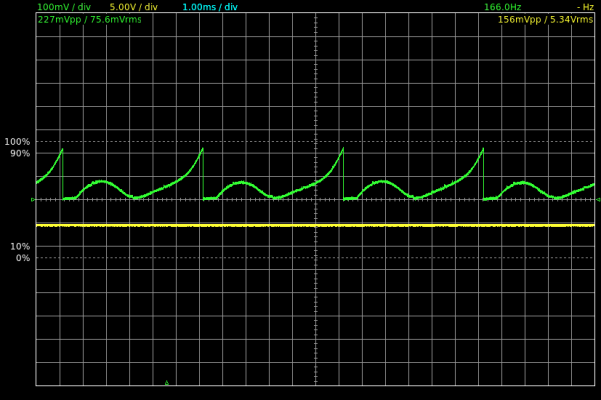
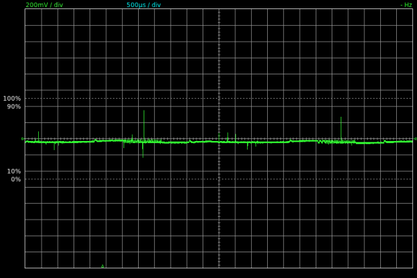
By the way, if I turn the potmeter, the maximum current will look like this:
So its 200 mV peak, that means the current is 400mA maximum!
Its not even one quarter of the maximum current. So Im back to my initial suspect, something is not right
So its 200 mV peak, that means the current is 400mA maximum!
Its not even one quarter of the maximum current. So Im back to my initial suspect, something is not right
|
Re: Stepper motor cant go fast November 21, 2008 08:59AM |
Registered: 16 years ago Posts: 204 |
Ups, I forgot to regulate the power supply to 12V. (it was on 7V)
Now the power supply isexactly on12V (12,03V to be exact)
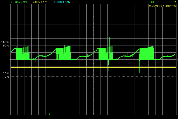
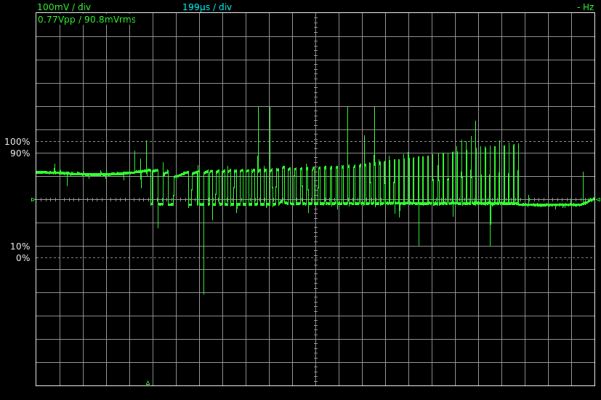
The waveform on Rsense:
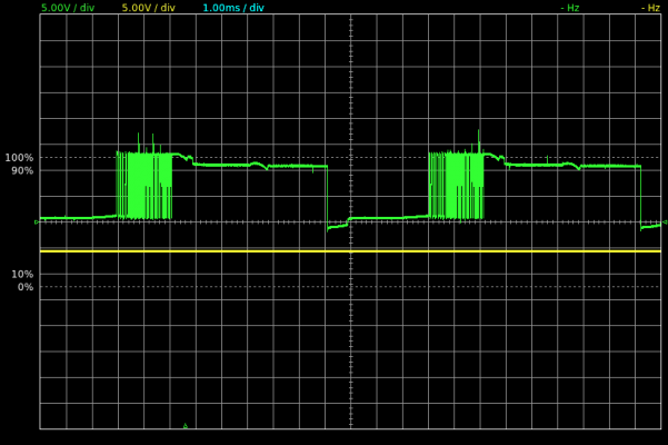
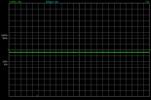
The waveform on output A:
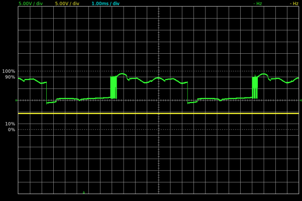
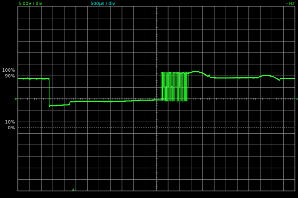
If I turn the potmeter more, the duty cycle does not really change, but the waveform become uglier (also the power supply indicate that he is delivering only 9V):
Now the power supply isexactly on12V (12,03V to be exact)
The waveform on Rsense:
The waveform on output A:
If I turn the potmeter more, the duty cycle does not really change, but the waveform become uglier (also the power supply indicate that he is delivering only 9V):
|
Anonymous User
Re: Stepper motor cant go fast November 21, 2008 11:20AM |
|
Re: Stepper motor cant go fast November 21, 2008 03:56PM |
Admin Registered: 17 years ago Posts: 7,879 |
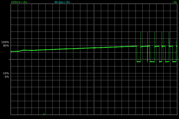
The first picture shows 300mV so about 0.6A. You are stepping every 6ms but it takes 4ms for the current to reach is full value due to the inductance of the motor.
The second picture shows ~10V so you are losing 2V in the L298. You only see the chopping half as often as it only chops the high side drive.
On the third picture you have raised the current so you only get 8V across the motor. It takes nearly all the cycle for the current to build up to the point where it starts chopping. Is the voltage from your PSU dropping, or is it all loss in the L298? It will lose about 4V when loaded to 2A but the rate at which the current rises it doesn't look like you get to 2A at this speed.
One thing that does not look correct is the sense waveform. When the current reaches the target value the high side drive turns off but current should still flow through the coil, due to its inductance, and through the sense resistor. You should see the sense voltage start to fall slowly and then the high side turns on again and it rises again. So it should hover around the preset value. It looks like it drops to zero between each chop cycle.
Please can you zoom in and show the current chopping waveform. It may just be spikes going to zero.
[www.hydraraptor.blogspot.com]
|
Re: Stepper motor cant go fast November 26, 2008 05:31AM |
Registered: 16 years ago Posts: 204 |
> Please can you zoom in and show the current chopping waveform. It may
> just be spikes going to zero.
Sure, I will repeat the experience, and zoom into. (sadly in qtdso I can zoom in when im measuring the circuit, I cant zoom afterwards or
save my data (for later observation).)
Summarizing:
I built three boards. It turned out finally, that on my second
board I had a short circuit (thanks to the oscilloscope I was able to
determine where the error is, after 3-4 hour poking around).
And on the third board the l298N failed, out1 (leg 2) to raise the voltage about 1V (the waveform otherwise looked good) instead of 12V.
And with this fault the l297 chips overheated, and failt too. (I dont know why). I didnt know this, so I was constantly replacing l297 with other board's l297, so at the end, I broked two l297 completely and one
broked so, that it works if I switch on and off the 5V 2-3 times. (complete mistery to me).
Probably the l298N failed because of insufficient cooling (too little heatsink), but Im not sure. I couldnt find on this board short circuit or open circuit (however I resoldered some of the pins), so I cant be certain.
What pissed me off, that I bought l297 for about 9$ and l298 for about 8$. And I discovered an other shop here, where these chips costs 2.5 times less (so about 3$ and 4$). So I spended 55$ more in the end (including the broken chips too (3*l297+1*l298)).
I could be buyed those chips (3*l297+3*l298) for about 21$ (I spended totally about 76$)
So an advice to the end:
When soldering everything, do not connect stepper motor to the output. Without the motor all the four output led (or 2 bicolor led) should be lighting. If not, there is an error somewhere.
Edited 1 time(s). Last edit at 11/26/2008 05:50AM by khiraly.
|
Re: Stepper motor cant go fast / cheaper stepper chips? November 26, 2008 06:59AM |
Registered: 15 years ago Posts: 251 |
|
Re: Stepper motor cant go fast November 26, 2008 08:13AM |
Registered: 16 years ago Posts: 204 |
Larry: It's a hungarian store located at Budapest.
Site: [www.hqelektronik.hu]
The price is 689.98HUF (from five: 611.12HUF), which means 3.44USD and 3.04USD respectively.
I dont think it is a viable solution outside of Hungary because of shipping costs.
Site: [www.hqelektronik.hu]
The price is 689.98HUF (from five: 611.12HUF), which means 3.44USD and 3.04USD respectively.
I dont think it is a viable solution outside of Hungary because of shipping costs.
|
Re: Stepper motor cant go fast November 26, 2008 08:27AM |
Registered: 16 years ago Posts: 204 |
So now a bit of photo-tour.
I have repeated the procedure, I have zoomed-in images too.
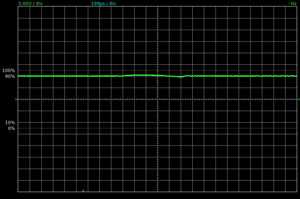
When "normal" current was set, the waveform of the power supply (+12V) looked like this:
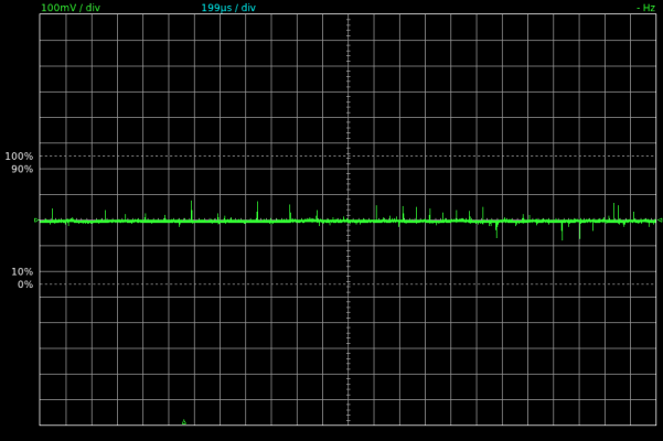
The GND (-12V) of the power supply looked like this (zoomed-in).
When zoomed out there were about 2V shift (i dont have that image, but
I do have when the current was high). So it looks like
there is only 10V, but it was 12V, because the GND was below the X axe.
This image is only indicating the noise i think.
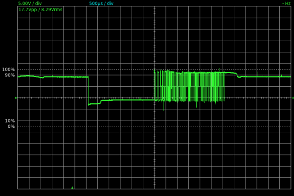
The waveform on output A (timebase: 500us/div):
The zoomed-in waveform of output A (timebase:200us/div):
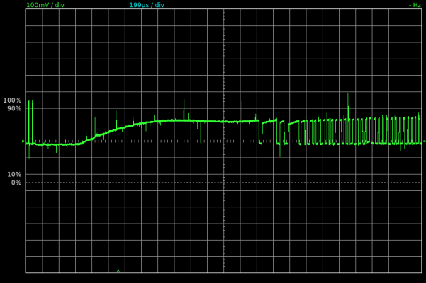
The waveform on rsense A (R1 on schematic):
The waveform on rsense A zoomed-in:
I will post an another message, for the high current settings.
(can not post more images)
Edited 1 time(s). Last edit at 11/26/2008 08:35AM by khiraly.
|
Re: Stepper motor cant go fast November 26, 2008 08:35AM |
Admin Registered: 17 years ago Posts: 7,879 |
I don't undertand the current waveform. The current through an inductor cannot change instantaneously as the wafeform seems to show. I would expect it to hover around the set point with a saw tooth wafeform rather than a square wave.
See the diagrams on this page: [www.stepperworld.com]
[www.hydraraptor.blogspot.com]
See the diagrams on this page: [www.stepperworld.com]
[www.hydraraptor.blogspot.com]
|
Re: Stepper motor cant go fast November 26, 2008 08:41AM |
Registered: 16 years ago Posts: 204 |
So now the images with higher current settings.
The 12V supply (+12V):
The GND (-12V):
The zoomed-in GND(-12V):
The output A:
The waveform of rsense A:
A zoomed-in image of rsense A:
An another zoomed-in image of rsense A:
The 12V supply (+12V):
The GND (-12V):
The zoomed-in GND(-12V):
The output A:
The waveform of rsense A:
A zoomed-in image of rsense A:
An another zoomed-in image of rsense A:
|
Re: Stepper motor cant go fast November 26, 2008 08:56AM |
Registered: 16 years ago Posts: 204 |
nophead: I would expect the same, and it is really weird.
Again the data of the stepper motor:
1.5mH of one coil
0.9Ohm of one coil.
It is connected as bipolar serial, so I think the above becomes:
3mH of two coil connected serial.
1.8 Ohm of two coil connected serial.
There is a 0.5Ohm resistence (which I measure as 0.6 Ohm with my multimeter) in series with them, so finally we have this load:
3mH inductance
2.4 Ohm of resistance (2*0.9 + 0.6)
The question: What is the skew rate of this load:
So if we change the voltage from 0 to 12V what should be the response time of the load?
There are two possibilities:
- what we see is not normal (maybe my oscilloscope does not have enough sampling, or the programs fault, or something else)
- the skew rate is normal, so i should increase the switchink frequency, which is about 19khz right now (using FFT analysis).
Would be nice, if somebody could repeate my exercise armed with an oscilloscope. The sample program is precedent page.
Edited 1 time(s). Last edit at 11/26/2008 08:59AM by khiraly.
|
Re: Stepper motor cant go fast November 26, 2008 09:04AM |
Admin Registered: 17 years ago Posts: 7,879 |
When the current reaches the target the top transistor should switch off. The voltage on the inductor should swing slightly negative until the diode conducts allowing the current to continue flowing round the loop consisting of the coil, the diode, the bottom transisor and the sense resistor. The current should then decay slowly because di/dt = V/L and V is small. I.e. it should fall slower than it rises.
[www.hydraraptor.blogspot.com]
[www.hydraraptor.blogspot.com]
|
Re: Stepper motor cant go fast November 26, 2008 09:57AM |
Admin Registered: 17 years ago Posts: 7,879 |
It is like what would happen if the bottom diodes were missing, or not connected to ground.
[www.hydraraptor.blogspot.com]
[www.hydraraptor.blogspot.com]
|
Re: Stepper motor cant go fast November 26, 2008 11:00AM |
Registered: 16 years ago Posts: 204 |
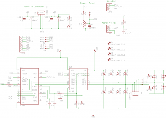
So you mean all the D1, D2, D3, D4 diodes?
high resolution: [khiraly.googlepages.com]
I will double check them. What is worst, that all my three boards are identical now (same waveform), so can not be really a wrong soldering...
high resolution: [khiraly.googlepages.com]
I will double check them. What is worst, that all my three boards are identical now (same waveform), so can not be really a wrong soldering...
|
Re: Stepper motor cant go fast November 26, 2008 11:29AM |
Registered: 16 years ago Posts: 204 |
I have double checked all the 8 diodes (D1-D8) on all the three boards.
They are as on the schematic.
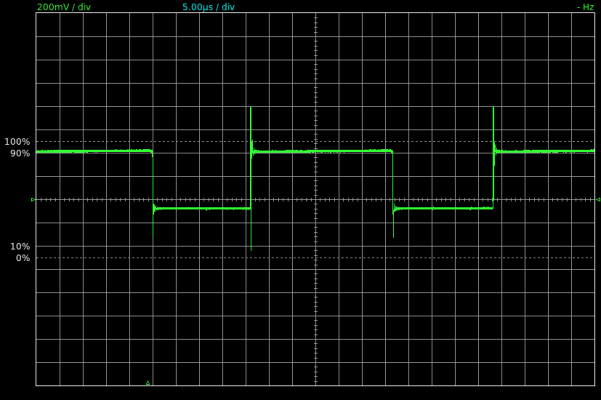
I also zoomed really into the waveform on the rsenseA:
And an another shot:
Do you think its worth trying with an another oscilloscope? (with an analog one)
By the way, the waveform looks to me like an attenuation. I have seen waveforms like this in PI(D) controllers.
They are as on the schematic.
I also zoomed really into the waveform on the rsenseA:
And an another shot:
Do you think its worth trying with an another oscilloscope? (with an analog one)
By the way, the waveform looks to me like an attenuation. I have seen waveforms like this in PI(D) controllers.
|
Re: Stepper motor cant go fast November 26, 2008 11:46AM |
Registered: 15 years ago Posts: 100 |
Sorry if this is too much like 'is it plugged in' type advice.
The diodes being the wrong way around would look the same as them not being there. A basic test of the orientation would be that all the non-stripped ends of D1->D4 should be connected to earth and the striped ends of D5->D8 should be connected to 12V. If that doesn't show try checking if pin 1 is connected to the striped end of D1 and the non-striped end of D5, pin 2 to D2 and D6 etc
nophead: Am I right in thinking a lack of diodes would also cause the spikes of almost 24V or -12V when the transistor is turned back on. The only place the current, driven by the inductor, can go is into charging the capacitance of the rest of the circuit. As the capacitance of the wire and the gates attached to the circuit is very low this causes the voltage to rise very quickly until it is greater than the breakdown voltage of the H bridge transistors.
|
Re: Stepper motor cant go fast November 26, 2008 12:02PM |
Admin Registered: 17 years ago Posts: 7,879 |
Yes the current circulates through D1-D4 when the top transistors are turned off while chopping.
If they were backwards they would short the winding to ground.
If open the pin would try to go negative but perhaps would cause a parasytic diode in the L298 to conduct. In which case the current would no longer flow down the sense pin. Are the diodes definitely connected to ground. I.e. does the schematic match the PCB?
Another way it could happen is if both transistors are turned off during chopping instead of just the top one. Maybe that is what the L297 does and just has a fixed off time.
[www.hydraraptor.blogspot.com]
|
Re: Stepper motor cant go fast November 26, 2008 12:10PM |
Registered: 15 years ago Posts: 100 |
Actually thinking about it a bit more, reversing one diode would pull that pin to gnd or 12v and reversing two would look like a short. So even less helpful than I imagined ;-}
The complete drop to 0v when the bridge is 'off' is very odd, I think nophead's line of reasoning was if the current isn't going through the sense resistor where is it going?
Does the L297 control the two bridges separately? as if it does then there is a chance that the coils are wired something like A->C and B->D instead of A->B & C->D.
Monitoring both Sense Resistors would probably show if something like this was happening.
The drop to zero also seems to be causing the L297 to not go below 50% duty cycle.
|
Re: Stepper motor cant go fast November 26, 2008 12:42PM |
Registered: 16 years ago Posts: 204 |
> The diodes being the wrong way around would look the same as them not
> being there. A basic test of the orientation would be that all the
> non-stripped ends of D1->D4 should be connected to earth and the
> striped ends of D5->D8 should be connected to 12V. If that doesn't
> show try checking if pin 1 is connected to the striped end of D1 and
> the non-striped end of D5, pin 2 to D2 and D6 etc
The schematic is here:
[khiraly.googlepages.com]
The pcb layout is here:
[khiraly.googlepages.com]
The photo of the board is here:
[khiraly.googlepages.com]
[khiraly.googlepages.com]
So I think the diodes are mounted as they should. But could you double-check for me please?
Also on the precedent page, there are one more photo (with changed heatsink).
I have also checked the diodes (with multimeter) all the eight.
The eagle schematic and board design are in synchron, so if I highlight one part in schematic it will also highlight on the board too (and vice versa). So the diodes should be fine. (comparing the board screenshot with the photo)
But please, ideas are welcome, I will check every one, because you think too that somethink is wrong.
Edited 1 time(s). Last edit at 11/26/2008 12:43PM by khiraly.
|
Re: Stepper motor cant go fast November 26, 2008 01:08PM |
Registered: 16 years ago Posts: 204 |
> Does the L297 control the two bridges separately?
Datasheet are here: [khiraly.googlepages.com]
The two coil of the stepper motor (A-B and C-D) are controled separately. The input In1(leg 5) and In2 (leg 7) controls one coil (A- , and In3(leg 10) and In4(leg 12) controls the other coil (C-D).
> as if it does then there is a chance that the coils are wired
> something like A->C and B->D instead of A->B & C->D.
It is imaginable, that I have miswired the stepper motor.
datasheet are here: [www.stappenmotor.nl]
the type of my motor: 23LC051-025-8W-F10-1.0
And I wired as in my first reply:
> Each windings has 1.8 Ohm resistance.
> I connected as bipolar series, so:
> Yellow, blue to A,B (shortened red, black together)
> Green, white to C,D (shortened brown, orange together)
> So the resistence are 3.6 Ohm for each windings (A-B, C-D).
Maybe it is not like in the datasheet. The pairs are sure:
Yellow, Red (1.8 Ohm)
Black, Blue (1.9 Ohm
Green, Brown (1.8 Ohm)
Orange, White (1.8 Ohm)
Which combination should I try?
> Monitoring both Sense Resistors would probably show if something like
> this was happening.
Unfortunetly I can only monitor one Rsense at the time (channel B seems broken on this oscilloscope, or the qtdso is).
But the waveform is the same on RsenseA and B. No idea if there is a time shift tough.
Questions:
Do you think disconnecting some diodes from D1-D8 and monitoring the waveform make sense? If so which one(s) should I desolder?
Do you think the stepper motor are wired wrongly? If so, can it explain the above waveforms? Which combination should I try?
(just be on the safe side and connect everything as bipolar serial for be below the 2A/coil limit. The motor are rated to 2.5A)
Datasheet are here: [khiraly.googlepages.com]
The two coil of the stepper motor (A-B and C-D) are controled separately. The input In1(leg 5) and In2 (leg 7) controls one coil (A-
 , and In3(leg 10) and In4(leg 12) controls the other coil (C-D).
> as if it does then there is a chance that the coils are wired
> something like A->C and B->D instead of A->B & C->D.
It is imaginable, that I have miswired the stepper motor.
datasheet are here: [www.stappenmotor.nl]
the type of my motor: 23LC051-025-8W-F10-1.0
And I wired as in my first reply:
> Each windings has 1.8 Ohm resistance.
> I connected as bipolar series, so:
> Yellow, blue to A,B (shortened red, black together)
> Green, white to C,D (shortened brown, orange together)
> So the resistence are 3.6 Ohm for each windings (A-B, C-D).
Maybe it is not like in the datasheet. The pairs are sure:
Yellow, Red (1.8 Ohm)
Black, Blue (1.9 Ohm
Green, Brown (1.8 Ohm)
Orange, White (1.8 Ohm)
Which combination should I try?
> Monitoring both Sense Resistors would probably show if something like
> this was happening.
Unfortunetly I can only monitor one Rsense at the time (channel B seems broken on this oscilloscope, or the qtdso is).
But the waveform is the same on RsenseA and B. No idea if there is a time shift tough.
Questions:
Do you think disconnecting some diodes from D1-D8 and monitoring the waveform make sense? If so which one(s) should I desolder?
Do you think the stepper motor are wired wrongly? If so, can it explain the above waveforms? Which combination should I try?
(just be on the safe side and connect everything as bipolar serial for be below the 2A/coil limit. The motor are rated to 2.5A)
|
Re: Stepper motor cant go fast November 26, 2008 01:27PM |
Registered: 16 years ago Posts: 204 |
I have used HER308 diodes, datasheet:
[khiraly.googlepages.com]
It has 75ns recovering time. It is not as simple, that this diodes are open so fast, that they can conduct of the coils current?
What should be the recovering time of these diodes? (100ns?)
[khiraly.googlepages.com]
It has 75ns recovering time. It is not as simple, that this diodes are open so fast, that they can conduct of the coils current?
What should be the recovering time of these diodes? (100ns?)
|
Re: Stepper motor cant go fast November 26, 2008 04:57PM |
Admin Registered: 17 years ago Posts: 7,879 |
khiraly,
Having looked at the datasheets I now see the sense waveform is correct. When the current limit is reached the L297 turns off the bottom transistor and turns on both top transistors. That means the current will recirculate through one top transistor and one top diode. It does not pass through the sense resistor, which is why the voltage across it drops to zero. The current through the coil will be a sawtooth like the diagram I referenced but the sense resistor only sees half of the waveform. This is to reduce the dissipation in the resistor. Sorry for the confusion.
The faster the recovery time of the diodes the better, less switching losses. They can't be too fast. 75ns is fast compared to your switching waveform so they are fine.
I think the waveforms show everything is working as intended. By connecting the coils in series you get four times the inductance, not twice.
The time constant of 6mH and 2.4R is L/R = 2.5ms. That means after 2.5ms the current will build up to about 2/3 of the final value it would get to when about 8V is applied. If you look at the sense waveform it is about 2.5ms for the current to build up from 0 to the point where it starts chopping. At the start of the cycle the current is flowing the other way so it takes another 2.5ms to get to zero. You don't see the reverse current in the sense resistor because of the diodes.
So in summary it is working correctly and is as fast as to be expected from a stepper. It should go four times faster in parallel mode. Increasing the supply voltage should make it faster as well. Remember the voltage across the motor is about 4V less than the supply. That means if you increase from 12V to say 24V then it should go 20/8 times faster. You should see the current rise faster on the scope. The more of the cycle where it has full current, the less torque reduction due to speed.
Also to run at high speed you need to start with longer steps and shorten them to get the rotational inertia of the motor moving. Just starting instantaneously like RepRap does, will not get anywhere near the maximum speed the motor is capable of.
[www.hydraraptor.blogspot.com]
|
Re: Stepper motor cant go fast November 26, 2008 06:21PM |
Registered: 16 years ago Posts: 204 |
First: thank you very much for your explanation. It helps a lot to understand things better.
> The current through the coil will be a sawtooth like the diagram I
> referenced but the sense resistor only sees half of the waveform. This
> is to reduce the dissipation in the resistor.
I do not see this sawtooth like diagram. If it is the waveform of the coil, I should see it on output A for example, right? Because that waveform is also switching to GND all the time.
Am I wrong here too?
|
Re: Stepper motor cant go fast November 26, 2008 06:36PM |
Admin Registered: 17 years ago Posts: 7,879 |
The voltage across the coil, which is what you see with the scope is a square wave, but the current rises and falls exponentially due to the inductance. You can only see the current rises in the sense resistor, but in the short gaps where the sense resistor voltage goes to zero the current is falling slightly. You can tell because when it turns on again you see the current is initially slightly less than when it turned off. You can deduce that the current starts off reversed, falls to zero, rises exponentially to the set value, then hovers around that value with a shallow sawtooth.
To see the true current waveform on a scope you would need to insert a small resistor in series with the coil and look at the voltage on each end of it with two channels and subtract them. Not possible if one channel is broken. If your scope is on a laptop then if you run it from battery it would be completely isolated so you could use one probe across the resistor and have you PC with 12V AC on its chassis.
[www.hydraraptor.blogspot.com]
|
Re: Stepper motor cant go fast November 27, 2008 01:37PM |
Registered: 16 years ago Posts: 204 |
nophead: For now, I declare the circuit boards as working, and I will advance with my other parts.
But Im thinking to by an DSO oscilloscope (owon), after I selled my analoge one. When I will have tha oscilloscope, I will repeate the experience with a resistance, and I will report back to this thread.
Thank you very much for your persistent help at this debugging. I have learned much.
But Im thinking to by an DSO oscilloscope (owon), after I selled my analoge one. When I will have tha oscilloscope, I will repeate the experience with a resistance, and I will report back to this thread.
Thank you very much for your persistent help at this debugging. I have learned much.
|
Re: Stepper motor cant go fast November 27, 2008 02:49PM |
Admin Registered: 17 years ago Posts: 7,879 |
By the way, why did you want more speed? What machine are you building?
[www.hydraraptor.blogspot.com]
[www.hydraraptor.blogspot.com]
|
Re: Stepper motor cant go fast November 28, 2008 03:02AM |
Registered: 16 years ago Posts: 204 |
> By the way, why did you want more speed? What machine are you building?
I have just suspected, that something is not right.
So I builded my board wrongly (given that, I home-made the pcbs too) short circuit or open circuit, wrongly soldered or whatever.
I suspected more, when you said, that its not normal if the stepper motor does not heat, and mine stays at room temperature or even colder.
Im building an Mcwire machine (it is the easiest one if you do not have the plastic parts for a reprap) with some modifications.
The modifications include unit conversion (Im not able to buy things in imperial unit here in the middle of Europe), and revisited x,y,z stage movements (I consulted with a friend who happen to be a mechanical engineer).
So my stages will be floating on metal rod instead of aluminium channel, will have no 608 bearings for support, it will be just some teflon (ptfe) block drilled through mounted the plastic rectangles on it.
What I want to do with my reprap?
- making pcbs at home (Im making now with aid of an iron and laser printer)
- cutout some models from balsa wood
- use a thermoplastic extruder and build a reprap or another interesting plastic parts or some self modelled "inventory" things.
I do not want particulary fast speeds, just as the others. I have simply suspected, something is wrong.
Sorry, only registered users may post in this forum.
