Listening to the Prusa Mendel frame (and interpreting it)
Posted by Lanthan
|
Listening to the Prusa Mendel frame (and interpreting it) January 13, 2012 08:17PM |
Registered: 13 years ago Posts: 228 |
Time for some science 
The aim is to set the bases for some experimentation on frames designs, vibrations & resonance.
This may also provide a new way of evaluating and comparing different firmwares.
I am no way an expert in sound analysis, but I hope this will get you experimenting as the experimental material is well within reach - I hope to see further analyses published here.
Materials and methods
=================
A cross-braced (as per [www.thingiverse.com] ) Prusa Mendel (2011) fitted with lm8uu bearings, a cork gasket on the X stepper motor, SY42STH47-1684B stepper motors, ramps 1.25 and Pololu (16x microstepping) electronics, running Marlin V1.0 firmware, was recorded with a Zoom H2 handy recorder standing on its anti-vibration tripod, placed in direct contact and about 1 mm from the left z-bar support. Sampling rate was set at 48 KHz, 16 bit samples, mic gain set to "HIGH". The recordings were transferred from SD-card to a suitable personal computer running Audacity 1.3.12-beta, a free digital audio editor ( [audacity.sourceforge.net] ). Visualization tools used included Analyze -> Plot Spectrum and, on the track drop down menu, Spectrogram.
Recordings of the background sound (fans and power suply running) were also taken with the same hardware at the same place.
The Marlin firmware relevant configuration details were:
The machine printed infill gcode generated by Slic3r (0.6 beta, cloned 20120112), configurated with solid infill at 50 mm/s and other infill at 60 mm/s, in a linear pattern.
Expected frequencies
=================
Assuming a main contribution to frame vibrations derived from the X and Y stepper motor operation, the expected main frequencies are:
solid infill step frequency : 60 (mm per second) * 80 (steps per mm) = 4800 Hz
other infill step frequency : 50 (mm per second) * 80 (steps per mm) = 4000 Hz
as well as intermediary freqencies related to acceleration/deceleration, and different harmonics of the main freqencies.
Experimental Results
================
1. Background noise
================
Background noise was found to peak at -58 dB
Main observed peaks:
2. Operating noise
==============
main peaks:
637 Hz (-45 dB )
1022
1208
1685
2079
2681
3378 (-52 dB ) (G#7)
3999
4390 (-65.4 dB ) (C#8)
4526 (C#8)
4796
6742 (-61.7 dB ) (G#8)
10157 (D#9)
13517 Hz (G#9)
15287 (A#9)
Discussion
========
The origin of the peak at 637 Hz remains to be identified. This noise is continous and does not exactly correspond to the fan noise that appears in the background recordings.
The machine's operating noise is dominated by low frequency noise in the 250 to 800 Hz range, then a complex group of peaks from 1711 Hz to 3378 Hz
In the expected stepper frequencies range, we can see lesser peaks at 3999 Hz and 4390 Hz
The frequencies in the range up from 1700 Hz appear to follow a trapezoidal pattern corresponding to acceleration and deceleration during the linear fill. Interestingly enough, emissions at about 8000 Hz mark the deceleration phase. The infill is large enough so that the nominal feed can be reached by the firmware. That maximal speed phase appears in the graphics as a plateau.
Direction inversion at the end of a loop is marked by a sharp transient (t) at 8000 to 9000 Hz
Conclusion
=========
The observed dominant frequencies are lower than expected with a "stepper only" hyopthesis. Alternatively, the firmware might not be operating at the nominal speed.
Further research should concentrate on the elucidation of the origin of the different frequencies (frame / steppers). The suspected contribution of the frame appears very large.
To Do
=====
- Compare different firmwares (Marlin / Sprinter / Repetier) with the same gcode file
- Compare different frames (cupcake / Prusa Mendel... Mendel90...) with same firmware and gcode
- Compare differents speeds for a given frame and firmware
- Test different methods of isolating the frame and the motors.
- Test recording the frame with a piezo
- Further analyses and plots with R and [rug.mnhn.fr]
- Generate 3D Spectrograms in VRML, convert 'em to STL and...
------------
Note: the standalone recorder can be replaced by a microphone and direct recordng to the computer.
Edited 9 time(s). Last edit at 01/16/2012 03:57PM by Lanthan.
The aim is to set the bases for some experimentation on frames designs, vibrations & resonance.
This may also provide a new way of evaluating and comparing different firmwares.
I am no way an expert in sound analysis, but I hope this will get you experimenting as the experimental material is well within reach - I hope to see further analyses published here.
Materials and methods
=================
A cross-braced (as per [www.thingiverse.com] ) Prusa Mendel (2011) fitted with lm8uu bearings, a cork gasket on the X stepper motor, SY42STH47-1684B stepper motors, ramps 1.25 and Pololu (16x microstepping) electronics, running Marlin V1.0 firmware, was recorded with a Zoom H2 handy recorder standing on its anti-vibration tripod, placed in direct contact and about 1 mm from the left z-bar support. Sampling rate was set at 48 KHz, 16 bit samples, mic gain set to "HIGH". The recordings were transferred from SD-card to a suitable personal computer running Audacity 1.3.12-beta, a free digital audio editor ( [audacity.sourceforge.net] ). Visualization tools used included Analyze -> Plot Spectrum and, on the track drop down menu, Spectrogram.
Recordings of the background sound (fans and power suply running) were also taken with the same hardware at the same place.
The Marlin firmware relevant configuration details were:
#define DEFAULT_AXIS_STEPS_PER_UNIT   {80,80,3200/1.25,571.428571429}
#define DEFAULT_MAX_FEEDRATE          {500, 500, 5, 450}
#define DEFAULT_MAX_ACCELERATION      {900,900,80,10000}
The machine printed infill gcode generated by Slic3r (0.6 beta, cloned 20120112), configurated with solid infill at 50 mm/s and other infill at 60 mm/s, in a linear pattern.
Expected frequencies
=================
Assuming a main contribution to frame vibrations derived from the X and Y stepper motor operation, the expected main frequencies are:
solid infill step frequency : 60 (mm per second) * 80 (steps per mm) = 4800 Hz
other infill step frequency : 50 (mm per second) * 80 (steps per mm) = 4000 Hz
as well as intermediary freqencies related to acceleration/deceleration, and different harmonics of the main freqencies.
Experimental Results
================
1. Background noise
================

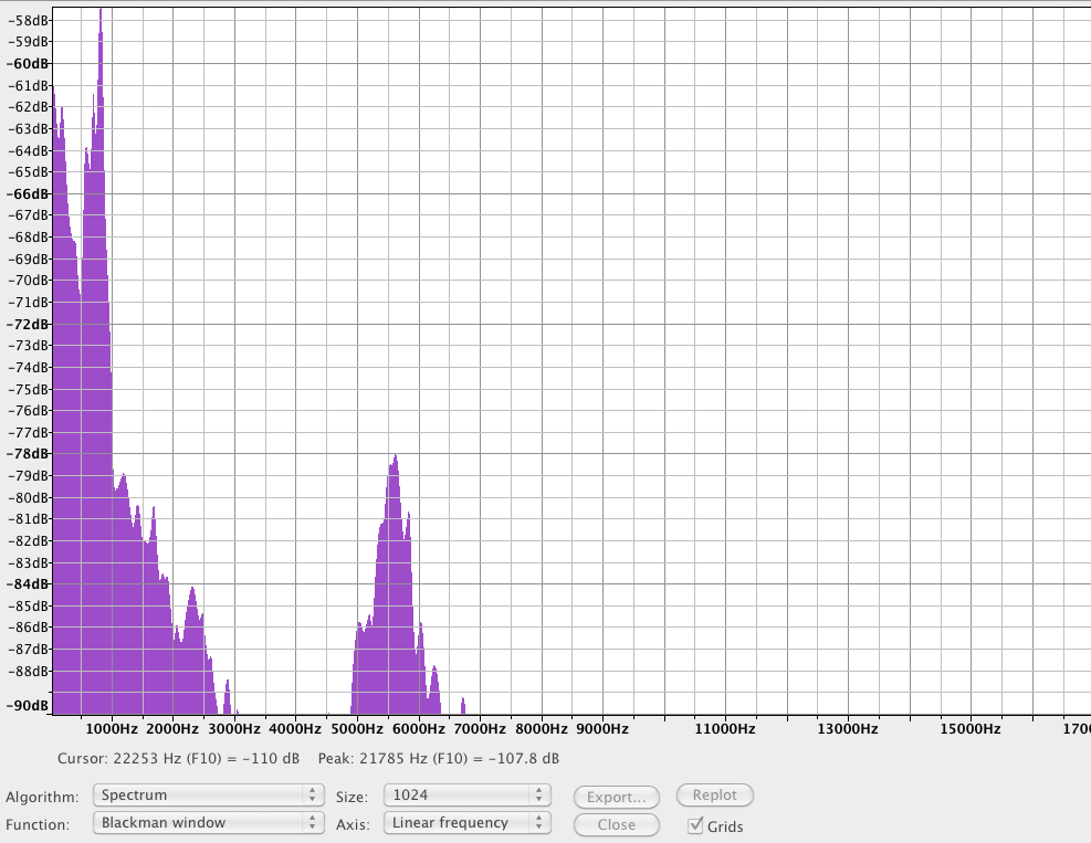
Background noise was found to peak at -58 dB
Main observed peaks:
161 Hz  (-61 dB )
826-883 Hz  (-58 dB )
5693 Hz (-78 dB )

2. Operating noise
==============


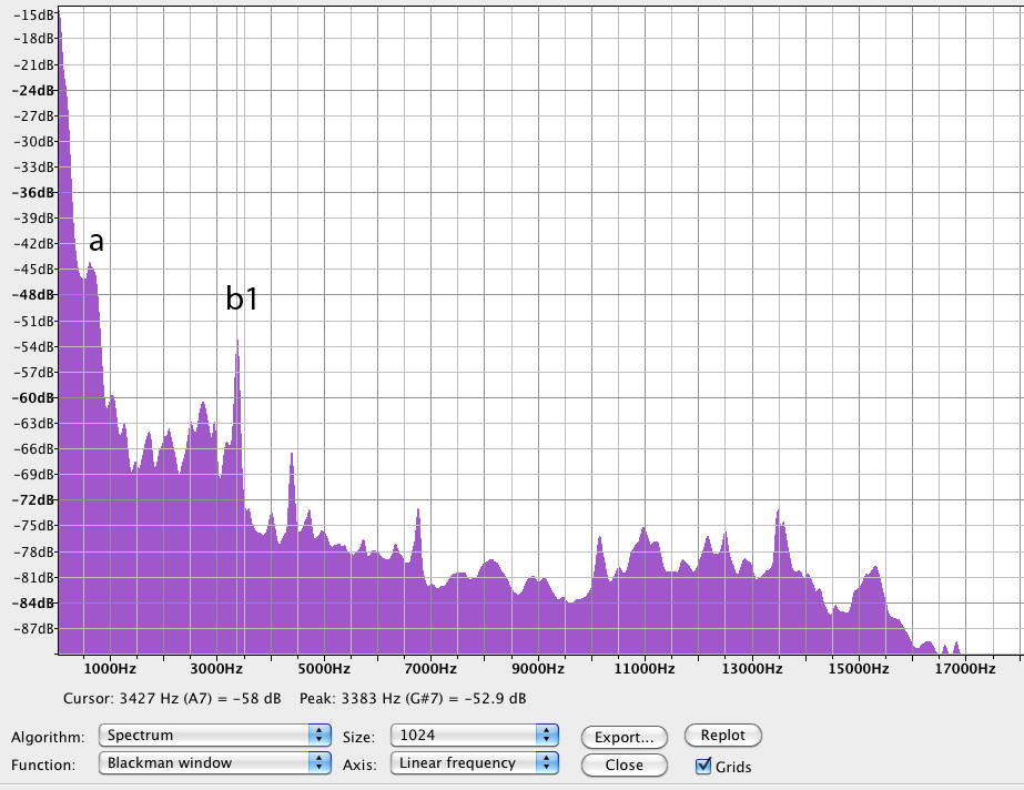
main peaks:
637 Hz (-45 dB )
1022
1208
1685
2079
2681
3378 (-52 dB ) (G#7)
3999
4390 (-65.4 dB ) (C#8)
4526 (C#8)
4796
6742 (-61.7 dB ) (G#8)
10157 (D#9)
13517 Hz (G#9)
15287 (A#9)
Discussion
========
The origin of the peak at 637 Hz remains to be identified. This noise is continous and does not exactly correspond to the fan noise that appears in the background recordings.
The machine's operating noise is dominated by low frequency noise in the 250 to 800 Hz range, then a complex group of peaks from 1711 Hz to 3378 Hz
In the expected stepper frequencies range, we can see lesser peaks at 3999 Hz and 4390 Hz
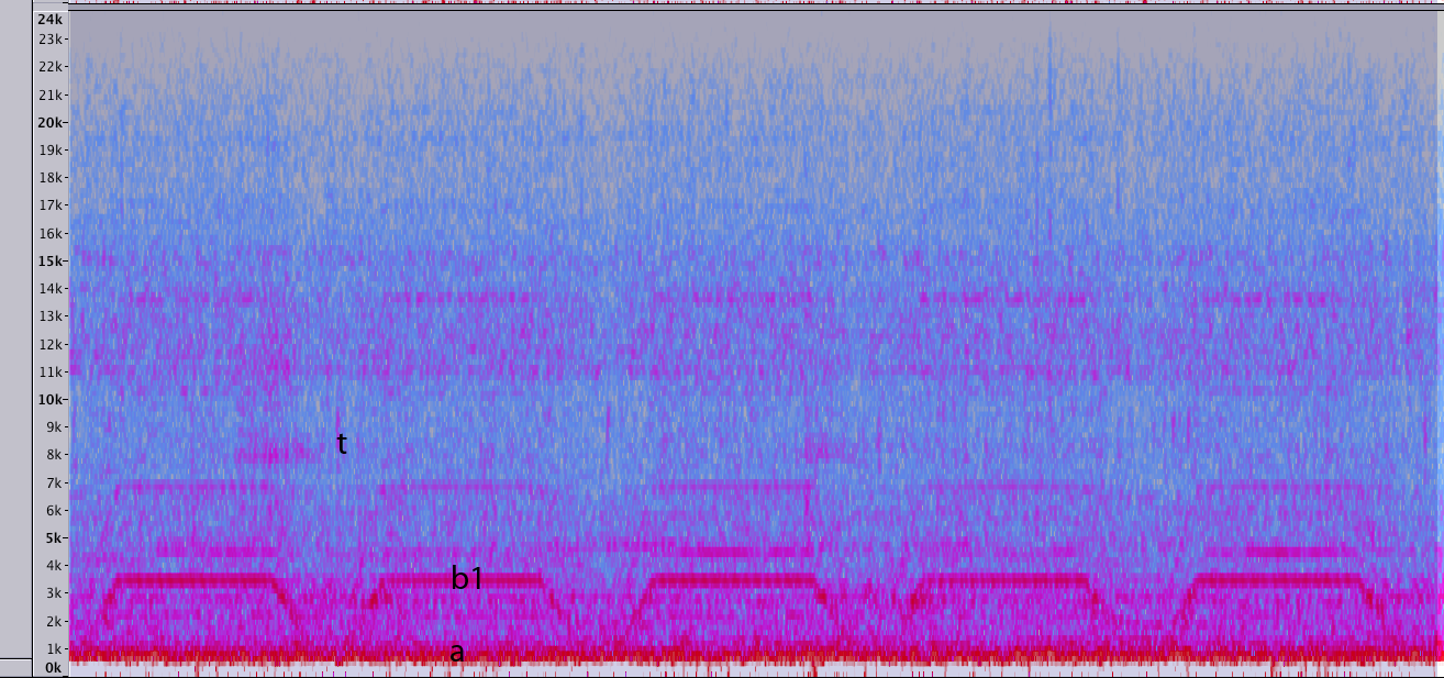
The frequencies in the range up from 1700 Hz appear to follow a trapezoidal pattern corresponding to acceleration and deceleration during the linear fill. Interestingly enough, emissions at about 8000 Hz mark the deceleration phase. The infill is large enough so that the nominal feed can be reached by the firmware. That maximal speed phase appears in the graphics as a plateau.
Direction inversion at the end of a loop is marked by a sharp transient (t) at 8000 to 9000 Hz
Conclusion
=========
The observed dominant frequencies are lower than expected with a "stepper only" hyopthesis. Alternatively, the firmware might not be operating at the nominal speed.
Further research should concentrate on the elucidation of the origin of the different frequencies (frame / steppers). The suspected contribution of the frame appears very large.
To Do
=====
- Compare different firmwares (Marlin / Sprinter / Repetier) with the same gcode file
- Compare different frames (cupcake / Prusa Mendel... Mendel90...) with same firmware and gcode
- Compare differents speeds for a given frame and firmware
- Test different methods of isolating the frame and the motors.
- Test recording the frame with a piezo
- Further analyses and plots with R and [rug.mnhn.fr]
- Generate 3D Spectrograms in VRML, convert 'em to STL and...
------------
Note: the standalone recorder can be replaced by a microphone and direct recordng to the computer.
Edited 9 time(s). Last edit at 01/16/2012 03:57PM by Lanthan.
Attachments:
open | download - 20120113_background_spectrogram.png (474 KB)
open | download - 20120113_background_spectrum.png (65.2 KB)
open | download - 20120113_prusa_xbraced marlin_50_spectrum.png (54.9 KB)
open | download - 20120113_prusa_xbraced_fill_50_spectrogram.png (561.3 KB)
open | download - 20120113_prusa_xbraced_marlin_fill_50_spectrum.txt (11.8 KB)
|
Re: Listening to the Prusa Mendel frame (and interpreting it) January 16, 2012 12:26PM |
Registered: 13 years ago Posts: 601 |
|
Re: Listening to the Prusa Mendel frame (and interpreting it) January 16, 2012 03:53PM |
Registered: 13 years ago Posts: 228 |
Buback Wrote:
-------------------------------------------------------
> All this is way over my head, but good work.
> Something I've wondered before is how the belts
> resonate, and if it has any impact?
There is a basic primer on standing waves here, complete with nice videos. The case that most interests us is "both ends clamped".
[www.ap.smu.ca]
With our little experience, we can see clearly a G# resonant series with the peaks at :
3378 Hz (G#7), 6742 (G#8), 13517 (G#9)
eacho octave corresponds to a doubling of frequency.
As we do not see a strong peak at 3378 / 2 = 1689 Hz, I think we can affirm that the fundamental mode is at 3378 Hz
This fundamental frequency is distinct from the (theoretical) stepper rate.
Further verifications should include determining if the firmware is actually running the X and Y steppers at the nominal rate.
If this is confirmed, we should have a look at what happens when the steppers are run at exactly 33788/60 = 56.3 mm/s, the exciting frequency.
We need more resolution to see what happens in the band below 1KHz, where the stronger vibrations are concentrated
Design thoughts:
- We should "de-tune" our designs so as to minimize resonances
- Building machines with many rods of equal length should probably be avoided.
- There is a point for supported smooth rod (hum but it is expensive...)
- There is theoretically a possibility to "de-tune" stepper driving in order to minimize or even counter frame vibration
- We should expect better accuracy and less wear at some speeds, and decreased accuracy at others, in a non-linear relationship.
I wonder what are the the refresh times of cheaply available accelerometers
Edited 2 time(s). Last edit at 01/16/2012 04:18PM by Lanthan.
|
Re: Listening to the Prusa Mendel frame (and interpreting it) January 16, 2012 07:58PM |
Registered: 13 years ago Posts: 228 |
I have been hunting for formulas and constants,it is not yet clear to me which one I should use.
Here's one that seems to work.
and
where
U = natural frequency in radians per second
E = Young's modulus of elasticity
L = length
d = material density
f = frequency in cycles per second
Given the values for steel:
d = 7.8*10^3 (Kg*m^-3)
E = 2.2 " 10^11 (N * m^-2)
v = 5660 m s^-1 (speed of sound in steel, used for other calculations)
M8 steel round bar : 0.3950 Kg per m (used for other calculations)
M8 threaded rod: 0.319 Kg per m (used for other calculations)
Prusa Mendel nominal exposed studding length (plastic to plastic) L = 0.29 m
u = ( 3.14 / 0.29 ) * sqroot( 2.2 *10^11 / 7.8 *10^3)
u = 10.833078116 * sqroot (28.2051282 * 10^6)
u = 53108.500449551 rad / s
f = (53108.500449551)÷2π
f = 8452.48 Hz
Let us now look at the observation data. There is indeed a rather broad, rounded peak at about 8400 Hz. It is related to the deceleration transient and the direction reversal click. This could coorespond to the long frame studs vibrating in fundamental mode.
Still, we have many more bands to account for. bearings, x carriage, above all y carriage are the main suspects...
wanted: moment of inertia of m8 studding for transversal vibration...
Edited 1 time(s). Last edit at 01/16/2012 07:59PM by Lanthan.
Here's one that seems to work.
U = pi / L * sqroot( E / d )
and
f = U / 2pi
where
U = natural frequency in radians per second
E = Young's modulus of elasticity
L = length
d = material density
f = frequency in cycles per second
Given the values for steel:
d = 7.8*10^3 (Kg*m^-3)
E = 2.2 " 10^11 (N * m^-2)
v = 5660 m s^-1 (speed of sound in steel, used for other calculations)
M8 steel round bar : 0.3950 Kg per m (used for other calculations)
M8 threaded rod: 0.319 Kg per m (used for other calculations)
Prusa Mendel nominal exposed studding length (plastic to plastic) L = 0.29 m
u = ( 3.14 / 0.29 ) * sqroot( 2.2 *10^11 / 7.8 *10^3)
u = 10.833078116 * sqroot (28.2051282 * 10^6)
u = 53108.500449551 rad / s
f = (53108.500449551)÷2π
f = 8452.48 Hz
Let us now look at the observation data. There is indeed a rather broad, rounded peak at about 8400 Hz. It is related to the deceleration transient and the direction reversal click. This could coorespond to the long frame studs vibrating in fundamental mode.
Still, we have many more bands to account for. bearings, x carriage, above all y carriage are the main suspects...
wanted: moment of inertia of m8 studding for transversal vibration...
Edited 1 time(s). Last edit at 01/16/2012 07:59PM by Lanthan.
|
Re: Listening to the Prusa Mendel frame (and interpreting it) January 18, 2012 07:44AM |
Registered: 13 years ago Posts: 228 |
Time to kick in with more specialized tools.
I choose seewave, an R module
R
seewave
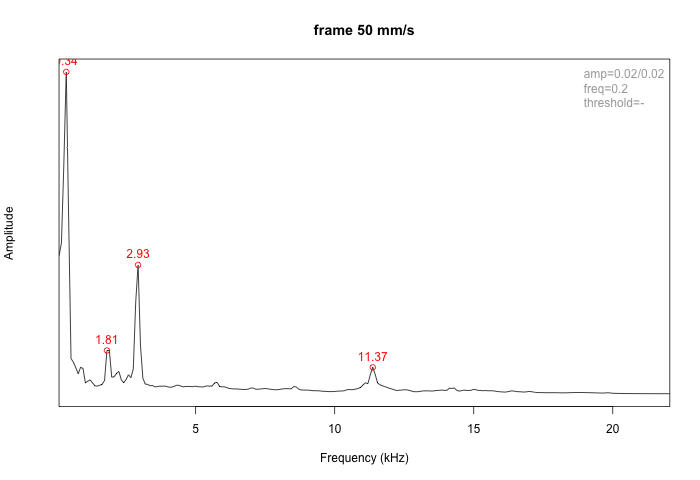
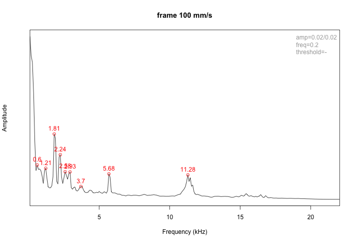
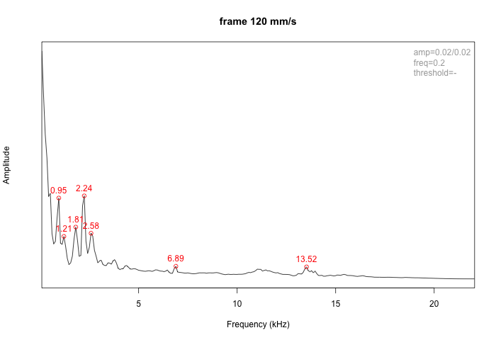
I prepared a rough simulation of a 45 degrees fill at 25, 50, 100 and 120 mm/s
and proceeded to record (48 KHz, 16 bit .wav) the frame (at the beforementioned place) and directly over the Y stepper motor.
Suitable frame and stepper recordings were then cut and saved as separate files. Further analysis and peak detection were carried on within R.
Here is the code:
The frame:
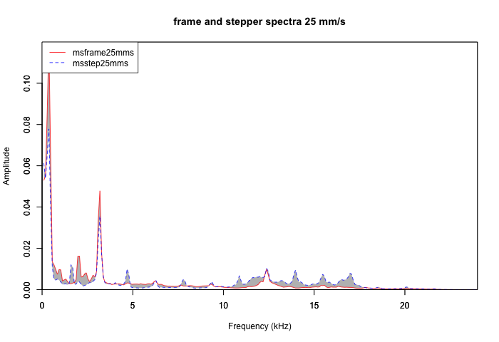
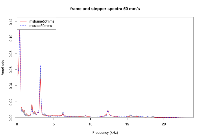
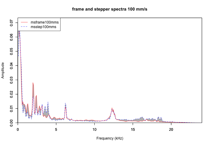
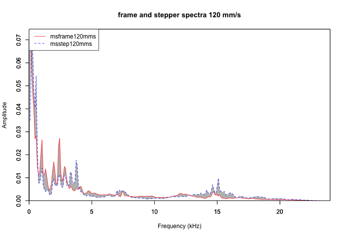
Differences between the frame and the stepper motor frequencies:
The respective contributions of the frame and the steppers to the vibration bands can be thus identified.
(to be continued)
Edited 4 time(s). Last edit at 01/18/2012 08:01AM by Lanthan.
I choose seewave, an R module
R
seewave
Sueur J., Aubin T., Simonis C. (2008). Seewave: a free modular tool for sound analysis
  and synthesis. Bioacoustics, 18: 213-226
I prepared a rough simulation of a 45 degrees fill at 25, 50, 100 and 120 mm/s
G92 X0.0 Y0.0 Z10.0
G1 F1500.0
G1 X80.0 Y80.0 F1500.0
G1 X120.0 Y120.0
G1 X80.0 Y80.0
G1 X120.0 Y120.0
G1 X80.0 Y80.0
G1 X120.0 Y120.0
etc.
and proceeded to record (48 KHz, 16 bit .wav) the frame (at the beforementioned place) and directly over the Y stepper motor.
Suitable frame and stepper recordings were then cut and saved as separate files. Further analysis and peak detection were carried on within R.
Here is the code:
# library('seewave') ;
# library('tuneR') ;
f<-48000 ;
y_step_25mms <- readWave("20120117_y_stepper_25mms.wav");
frame_25mms <- readWave("20120117_frame_25mms.wav");
y_step_50mms <- readWave("20120117_y_stepper_50mms.wav");
frame_50mms <- readWave("20120117_frame_50mms.wav");
y_step_100mms <- readWave("20120117_y_stepper_100mms.wav");
frame_100mms <- readWave("20120117_frame_100mms.wav");
y_step_120mms <- readWave("20120117_y_stepper_120_mms.wav");
frame_120mms <- readWave("20120117_frame_120_mms.wav");
sframe25mms <- spec(frame_25mms, f=f);
sstep25mms <- spec(y_step_25mms, f=f) ;
sframe50mms <- spec(frame_50mms, f=f);
sstep50mms <- spec(y_step_50mms, f=f) ;
sframe100mms <- spec(frame_100mms, f=f);
sstep100mms <- spec(y_step_100mms, f=f) ;
sframe120mms <- spec(frame_120mms, f=f);
sstep120mms <- spec(y_step_120mms, f=f) ;
msframe25mms <- meanspec(frame_25mms, f=f);
msstep25mms <- meanspec(y_step_25mms, f=f) ;
msframe50mms <- meanspec(frame_50mms, f=f);
msstep50mms <- meanspec(y_step_50mms, f=f) ;
msframe100mms <- meanspec(frame_100mms, f=f);
msstep100mms <- meanspec(y_step_100mms, f=f) ;
msframe120mms <- meanspec(frame_120mms, f=f);
msstep120mms <- meanspec(y_step_120mms, f=f) ;
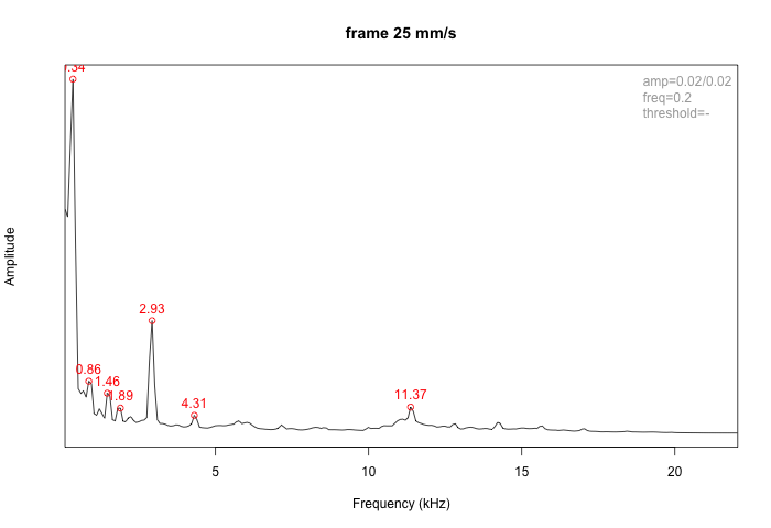
png(filename="frame_25_mms.png", width=700, height=480, units="px", pointsize=12)
fpeaks(meanspec(frame_25mms, PSD = FALSE, main = "frame 25 mm/s"), amp=c(0.02,0.02), freq=200, title=FALSE)
title(main = "frame 25 mm/s");
dev.off();
png(filename="frame_50_mms.png", width=700, height=480, units="px", pointsize=12)
fpeaks(meanspec(frame_50mms, PSD = FALSE, main = "frame 50 mm/s"), amp=c(0.02,0.02), freq=200, title=FALSE)
title(main = "frame 50 mm/s");
dev.off();
png(filename="frame_100_mms.png", width=700, height=480, units="px", pointsize=12)
fpeaks(meanspec(frame_100mms, PSD = FALSE, main = "frame 100 mm/s"), amp=c(0.02,0.02), freq=200, title=FALSE)
title(main = "frame 100 mm/s");
dev.off();
png(filename="frame_120_mms.png", width=700, height=480, units="px", pointsize=12)
fpeaks(meanspec(frame_120mms, PSD = FALSE, main = "frame 120 mm/s"), amp=c(0.02,0.02), freq=200, title=FALSE)
title(main = "frame 120 mm/s");
dev.off();
The frame:


Differences between the frame and the stepper motor frequencies:
png(filename="diff_25_mms.png", width=700, height=480, units="px", pointsize=12)
diffspec(msframe25mms,msstep25mms,f=f, plot=TRUE);
title(main = "frame and stepper spectra 25 mm/s");
dev.off();
png(filename="diff_50_mms.png", width=700, height=480, units="px", pointsize=12)
diffspec(msframe50mms,msstep50mms,f=f, plot=TRUE);
title(main = "frame and stepper spectra 50 mm/s");
dev.off();
png(filename="diff_100_mms.png", width=700, height=480, units="px", pointsize=12)
diffspec(msframe100mms,msstep100mms,f=f, plot=TRUE);
title(main = "frame and stepper spectra 100 mm/s");
dev.off();
png(filename="diff_120_mms.png", width=700, height=480, units="px", pointsize=12)
diffspec(msframe120mms,msstep120mms,f=f, plot=TRUE);
title(main = "frame and stepper spectra 120 mm/s");
dev.off();


The respective contributions of the frame and the steppers to the vibration bands can be thus identified.
(to be continued)
Edited 4 time(s). Last edit at 01/18/2012 08:01AM by Lanthan.
Attachments:
open | download - frame_25_mms.png (28.9 KB)
open | download - frame_50_mms.png (26.9 KB)
open | download - frame_100_mms.png (31.3 KB)
open | download - frame_120_mms.png (30.1 KB)
open | download - diff_25_mms.png (38.8 KB)
open | download - diff_50_mms.png (38.1 KB)
open | download - diff_100_mms.png (44.1 KB)
open | download - diff_120_mms.png (44.7 KB)
|
Re: Listening to the Prusa Mendel frame (and interpreting it) May 31, 2012 10:19PM |
Registered: 15 years ago Posts: 123 |
Awesome! This is the sort of analysis we need if reprap will ever get past the "hobby" stage. I don't know much about frequency analysis and virbational modes, but I am interested about any possible way to minimize the noise generated during printing (improve the "living room acceptability" factor).
I wonder if there are some sorts of cross bars we can print and attach to change the resonant frequencies of the threaded rods on the mendel frame. Another thing I can think of is.. nylon belt pulleys? There's little we can do about the stepper motor stepping vibration (besides switching to servos..) but at least we might be able to dampen where that vibration goes. Mendel90 is probably a good alternative (less rods), but then there are the large panels to serve as sound reflectors and amplifiers.
Keep up the good work!
|
Re: Listening to the Prusa Mendel frame (and interpreting it) June 01, 2012 10:08AM |
Registered: 12 years ago Posts: 809 |
I love this. Great work!
- akhlut
Just remember - Iterate, Iterate, Iterate!
[myhomelessmind.blogspot.com]
- akhlut
Just remember - Iterate, Iterate, Iterate!
[myhomelessmind.blogspot.com]
Sorry, only registered users may post in this forum.