|
Help With Prusa i3 Calibration December 09, 2014 10:14PM |
Registered: 9 years ago Posts: 6 |
Hello RepRap community,
I am new to 3d printing, and have been stuck for a few days troubleshooting and calibrating this printer. I am stuck as I am trying to calibrate it, but I am just getting the same steps per mm measurement everytime I adjust the settings in configuration.h
I have a Prusa I3
Nema 17 motors
17 tooth pulley
gt2 belt
Melzi board version 1.1
1/16 stepping
m5 Leadscrew
I have absolutely no idea where I should be looking to troubleshooting. I am have made good progress this far with no help, but really seem to be stuck here at this step.
Let me know if I can give you any more information, and I thank you for your time in advance!!
Quote
#ifndef REPRAPPRO_HUXLEY
#ifndef REPRAPPRO_MENDEL
#ifndef REPRAPPRO_MENDEL2
#error Uncomment one of #define REPRAPPRO_HUXLEY, REPRAPPRO_MENDEL, or REPRAPPRO_MENDEL2 at the start of the file Configuration.h
#endif
#endif
#endif
#ifndef REPRAPPRO_MELZI
#ifndef REPRAPPRO_SANGUINOLOLU
#error Uncomment one of #define REPRAPPRO_MELZI or REPRAPPRO_SANGUINOLOLU at the start of the file Configuration.h
#endif
#endif
#ifndef SERIAL_R
#error Uncomment one of #define SERIAL_R 10000 or 4700 at the start of the file Configuration.h
#endif
// ==============================================================================
// Uncomment this if you are experimenting, know what you are doing, and want to switch off some safety
// features, e.g. allow extrude at low temperature etc.
//#define DEVELOPING
// This configurtion file contains the basic settings.
// Advanced settings can be found in Configuration_adv.h
// BASIC SETTINGS: select your board type, temperature sensor type, axis scaling, and endstop configuration
//User specified version info of THIS file to display in [Pronterface, etc] terminal window during startup.
//Implementation of an idea by Prof Braino to inform user that any changes made
//to THIS file by the user have been successfully uploaded into firmware.
#define STRING_VERSION_CONFIG_H "2014-06-02-AB" //Personal revision number for changes to THIS file.
#define STRING_CONFIG_H_AUTHOR "RRP" //Who made the changes.
// This determines the communication speed of the printer
//#define BAUDRATE 250000
#define BAUDRATE 115200
//// The following define selects which electronics board you have. Please choose the one that matches your setup
// Sanguinololu 1.2 and above = 62
// Melzi 63
#ifdef REPRAPPRO_MELZI
#define MOTHERBOARD 63
#endif
//===========================================================================
//=============================Thermal Settings ============================
//===========================================================================
// Set this if you want to define the constants in the thermistor circuit
// and work out temperatures algebraically - added by AB.
// See [en.wikipedia.org]
// BETA is the B value
// RS is the value of the series resistor in ohms
// R_INF is R0.exp(-BETA/T0), where R0 is the thermistor resistance at T0 (T0 is in kelvin)
// Normally T0 is 298.15K (25 C). If you write that expression in brackets in the #define the compiler
// should compute it for you (i.e. it won't need to be calculated at run time).
// If the A->D converter has a range of 0..1023 and the measured voltage is V (between 0 and 1023)
// then the thermistor resistance, R = V.RS/(1023 - V)
// and the temperature, T = BETA/ln(R/R_INF)
// To get degrees celsius (instead of kelvin) add -273.15 to T
// This DOES assume that all extruders use the same thermistor type.
#define ABS_ZERO -273.15
#define AD_RANGE 16383
#ifdef REPRAPPRO_HUXLEY
// Bed thermistor: VISHAY BC COMPONENTS NTCS0603E3104FXT - All Huxleys with heated bed PCB
#define BED_BETA 4100.0
#define BED_NTC 100000.0
// Extruder thermistor: RS 198-961 100k ohm 10% DO-35 NTC thermistor - All Huxleys before 25/2/14
// #define E_BETA 3960.0
// #define E_NTC 100000.0
// Extruder thermistor: Digikey 480-3137-ND - All Huxleys shipped after 25/2/14
#define E_BETA 4138.0
#define E_NTC 100000.0
#endif
#ifdef REPRAPPRO_MENDEL
// Extruder thermistor: RS 198-961 100k ohm 10% DO-35 NTC thermistor - All Mendels before 1/4/13
#define E_BETA 3960.0
#define E_NTC 100000.0
// Bed thermistor: RS 484-0149; EPCOS B57550G103J - All Mendels before 1/4/13
#define BED_BETA 3480.0
#define BED_NTC 10000.0
#endif
#ifdef REPRAPPRO_MENDEL2
// Bed thermistor: Rapid 61-0446 ; Semitec 103GT-2 - All Mendel2 shipped after 1/4/13 (launch)
// #define BED_BETA 4126.0
// #define BED_NTC 10000.0
// Bed thermistor: Farnell 1299930 ; EPCOS B57863S103F040 - All Mendel2 shipped after 29/5/14
#define BED_BETA 3988.0
#define BED_NTC 10000.0
// Extruder thermistor: RS 198-961 100k ohm 10% DO-35 NTC thermistor - All Mendel2 shipped after 1/4/13 (launch)
// #define E_BETA 3960.0
// #define E_NTC 100000.0
// Extruder thermistor: Digikey 480-3137-ND - All Mendels shipped after 25/2/14
#define E_BETA 4138.0
#define E_NTC 100000.0
#endif
#define E_RS SERIAL_R
#define E_R_INF ( E_NTC*exp(-E_BETA/298.15) )
#define BED_RS SERIAL_R
#define BED_R_INF ( BED_NTC*exp(-BED_BETA/298.15) )
#define BED_USES_THERMISTOR
//#define HEATER_0_USES_THERMISTOR
#define HEATER_1_USES_THERMISTOR
//#define HEATER_2_USES_THERMISTOR
// Actual temperature must be close to target for this long before M109 returns success
#define TEMP_RESIDENCY_TIME 5 // (seconds)
#define TEMP_HYSTERESIS 5 // (C°) range of +/- temperatures considered "close" to the target one
#define TEMP_WINDOW 2 // (degC) Window around target to start the recidency timer x degC early.
// The minimal temperature defines the temperature below which the heater will not be enabled It is used
// to check that the wiring to the thermistor is not broken.
// Otherwise this would lead to the heater being powered on all the time.
#define HEATER_0_MINTEMP 1
#ifdef REPRAPPRO_MULTIMATERIALS
#define HEATER_1_MINTEMP 1
#define HEATER_2_MINTEMP 1
#endif
#define BED_MINTEMP 1
// When temperature exceeds max temp, your heater will be switched off.
// This feature exists to protect your hotend from overheating accidentally, but *NOT* from thermistor short/failure!
// You should use MINTEMP for thermistor short/failure protection.
#define HEATER_0_MAXTEMP 399
#ifdef REPRAPPRO_MULTIMATERIALS
#define HEATER_1_MAXTEMP 275
#define HEATER_2_MAXTEMP 275
#endif
#define BED_MAXTEMP 150
// PID settings:
// Comment the following line to disable PID and enable bang-bang.
#define PIDTEMP
#define PID_MAX 255 // limits current to nozzle; 255=full current
#define FULL_PID_BAND 150 // Full power is applied when pid_error[e] > FULL_PID_BAND
#ifdef PIDTEMP
//#define PID_DEBUG // Sends debug data to the serial port.
#define PID_INTEGRAL_DRIVE_MAX 125 //limit for the integral term
#define K1 0.95 //smoothing factor withing the PID
#define PID_dT 0.122 //sampling period of the PID
// RepRapPro Huxley + Mendel
#define DEFAULT_Kp 12.0
#define DEFAULT_Ki (2.2*PID_dT)
#define DEFAULT_Kd (80/PID_dT)
#endif // PIDTEMP
#ifndef DEVELOPING
//this prevents dangerous Extruder moves, i.e. if the temperature is under the limit
//can be software-disabled for whatever purposes by
#define PREVENT_DANGEROUS_EXTRUDE
#define EXTRUDE_MINTEMP 170
#define EXTRUDE_MAXLENGTH (200) //prevent extrusion of very large distances.
#else
#define BOGUS_TEMPERATURE_FAILSAFE_OVERRIDE
#endif
//===========================================================================
//=============================Mechanical Settings===========================
//===========================================================================
// Endstop Settings
#define ENDSTOPPULLUPS // Comment this out (using // at the start of the line) to disable the endstop pullup resistors
// The pullups are needed if you directly connect a mechanical endswitch between the signal and ground pins.
const bool X_ENDSTOPS_INVERTING = false; // set to true to invert the logic of the endstops.
const bool Y_ENDSTOPS_INVERTING = false; // set to true to invert the logic of the endstops.
const bool Z_ENDSTOPS_INVERTING = false; // set to true to invert the logic of the endstops.
// For Inverting Stepper Enable Pins (Active Low) use 0, Non Inverting (Active High) use 1
#define X_ENABLE_ON 0
#define Y_ENABLE_ON 0
#define Z_ENABLE_ON 0
#define E_ENABLE_ON 0 // For all extruders
// Disables axis when it's not being used.
#define DISABLE_X false
#define DISABLE_Y false
#define DISABLE_Z true
#define DISABLE_E false // For all extruders
#ifdef REPRAPPRO_MENDEL
#define AXES_MAX_LENGTHS {210, 210, 140}
#define INVERT_X_DIR false // for Mendel set to false, for Orca set to true
#define INVERT_Y_DIR true // for Mendel set to true, for Orca set to false
#define INVERT_Z_DIR false // for Mendel set to false, for Orca set to true
#define INVERT_E0_DIR true // for direct drive extruder v9 set to true, for geared extruder set to false
#define INVERT_E1_DIR true // for direct drive extruder v9 set to true, for geared extruder set to false
#define INVERT_E2_DIR true // for direct drive extruder v9 set to true, for geared extruder set to false
#endif
#ifdef REPRAPPRO_MENDEL2
#define AXES_MAX_LENGTHS {210, 210, 140}
#define INVERT_X_DIR true // for Mendel set to false, for Orca set to true
#define INVERT_Y_DIR true // for Mendel set to true, for Orca set to false
#define INVERT_Z_DIR false // for Mendel set to false, for Orca set to true
#define INVERT_E0_DIR true // for direct drive extruder v9 set to true, for geared extruder set to false
#define INVERT_E1_DIR true // for direct drive extruder v9 set to true, for geared extruder set to false
#define INVERT_E2_DIR true // for direct drive extruder v9 set to true, for geared extruder set to false
#endif
#ifdef REPRAPPRO_HUXLEY
#define AXES_MAX_LENGTHS {155, 150, 90}
#define INVERT_X_DIR false // for Mendel set to false, for Orca set to true
#define INVERT_Y_DIR false // for Mendel set to true, for Orca set to false
#define INVERT_Z_DIR false // for Mendel set to false, for Orca set to true
#define INVERT_E0_DIR true // for direct drive extruder v9 set to true, for geared extruder set to false
#define INVERT_E1_DIR true // for direct drive extruder v9 set to true, for geared extruder set to false
#define INVERT_E2_DIR true // for direct drive extruder v9 set to true, for geared extruder set to false
#endif
// ENDSTOP SETTINGS:
// Sets direction of endstops when homing; 1=MAX, -1=MIN
#define X_HOME_DIR -1
#define Y_HOME_DIR -1
#define Z_HOME_DIR -1
#define min_software_endstops true //If true, axis won't move to coordinates less than zero.
#define max_software_endstops true //If true, axis won't move to coordinates greater than the defined lengths below.
// The position of the homing switches. Use MAX_LENGTH * -0.5 if the center should be 0, 0, 0
#define X_HOME_POS 0
#define Y_HOME_POS 0
#define Z_HOME_POS 0
// INGS
#define NUM_AXIS 4 // The axis order in all axis related arrays is X, Y, Z, E
/*
We've shipped a number of different configurations of belt and pulley now, so probably need some ifdef statements! At the moment, they all get the same.
White polyurethane belt (T2.5), 14-tooth printed pulley: 91.4286 step per mm (Original Huxley, Legacy Mendel)
Black rubber belt (MXL), 17-tooth printed pulley: 92.635 step per mm (Huxley, Mendel Mono and Tri since 1/4/2013)
Black rubber belt (MXL), 18-tooth aluminium pulley: 87.489 step per mm (Huxley, Mendel Mono and Tri since 1/1/2014)
Also, two different extruders:
Original eMaker/RepRapPro-style: 920 steps per mm (Original Huxley, Legacy Mendel)
New version (NEMA14 and NEMA17): 660 steps per mm (Huxley, Mendel Mono and Tricolour since 1/4/2013)
*/
#ifdef REPRAPPRO_MENDEL
//#define X_MAX_LENGTH 200
//#define Y_MAX_LENGTH 200
//#define Z_MAX_LENGTH 180
//#define HOMING_FEEDRATE {10*60, 10*60, 1*60, 0} // set the homing speeds (mm/min)
//#define FAST_HOME_FEEDRATE {50*60, 50*60, 1*60, 0} // set the homing speeds (mm/min)
//#define DEFAULT_MAX_FEEDRATE {500, 500, 3, 45}
//#define DEFAULT_MAX_FEEDRATE {300, 300, 3, 45} // (mm/sec)
//#define DEFAULT_MAX_ACCELERATION {800,800,30,250} // X, Y, Z, E maximum start speed for accelerated moves. E default values
// X, Y, Z, E steps per mm
//#define DEFAULT_AXIS_STEPS_PER_UNIT {111.60,80,4000,300) // <- 14 tooth T2.5 belt + original extruder drive
#else
#ifdef REPRAPPRO_MENDEL2
//#define X_MAX_LENGTH 200
//#define Y_MAX_LENGTH 200
//#define Z_MAX_LENGTH 180
//#define HOMING_FEEDRATE {50*60, 50*60, 2.5*60, 0} // set the homing speeds (mm/min)
//#define FAST_HOME_FEEDRATE {50*60, 50*60, 1*60, 0} // set the homing speeds (mm/min)
//#define DEFAULT_MAX_FEEDRATE {500, 500, 3, 45}
//#define DEFAULT_MAX_FEEDRATE {300, 300, 3, 45} // (mm/sec)
//#define DEFAULT_MAX_ACCELERATION {800,800,30,250} // X, Y, Z, E maximum start speed for accelerated moves. E default values
// X, Y, Z, E steps per mm
//#define DEFAULT_AXIS_STEPS_PER_UNIT {100, 87.489, 4000, 660.0} // <- 18-tooth aluminium pulley
//#define DEFAULT_AXIS_STEPS_PER_UNIT {94.12, 92.635, 4000, 300} // <- 17-tooth printed pulley
#else
#define X_MAX_LENGTH 200
#define Y_MAX_LENGTH 200
#define Z_MAX_LENGTH 1x axis not
going as far 3d
#define HOMING_FEEDRATE {10*60, 10*60, 1*60, 0} // set the homing speeds (mm/min)
#define FAST_HOME_FEEDRATE {80*60, 80*60, 4*60, 0} // set the homing speeds (mm/min)
#define DEFAULT_MAX_FEEDRATE {500, 500, 5, 45} // (mm/sec)
#define DEFAULT_MAX_FEEDRATE {500, 500, 5, 45} // (mm/sec)
#define DEFAULT_MAX_ACCELERATION {1000,1000,50,250} // X, Y, Z, E maximum start speed for accelerated moves. E default values
// X, Y, Z, E steps per mm
//#define DEFAULT_AXIS_STEPS_PER_UNIT {87.489, 87.489, 4000, 660.0} // <- 18-tooth aluminium pulley
#define DEFAULT_AXIS_STEPS_PER_UNIT {105.41, 92.635, 4000, 660} // <- 17-tooth printed pulley
//#define DEFAULT_AXIS_STEPS_PER_UNIT {91.4286, 91.4286, 4000, 920.0} // <- 14 tooth T2.5 belt + original extruder drive
#endif
#endif
// Defaults changed by the G10 command
#define X_EXTRUDER_OFFSET 0
#define Y_EXTRUDER_OFFSET 0
#define Z_EXTRUDER_OFFSET 0
#define STANDBY_TEMP 140
#define PLA_TEMP 205
#define ABS_TEMP 250
#define DEFAULT_TEMP PLA_TEMP
#define DEFAULT_ACCELERATION 1000 // X, Y, Z and E max acceleration in mm/s^2 for printing moves
#define DEFAULT_RETRACT_ACCELERATION 1000 // X, Y, Z and E max acceleration in mm/s^2 for r retracts
//
#define DEFAULT_XYJERK 15.0 // (mm/sec)
#define DEFAULT_ZJERK 0.4 // (mm/sec)
#define DEFAULT_EJERK 15.0 // (mm/sec)
//===========================================================================
//=============================Additional Features===========================
//===========================================================================
// EEPROM
// the microcontroller can store settings in the EEPROM, e.g. max velocity...
// M500 - stores paramters in EEPROM
// M501 - reads parameters from EEPROM (if you need reset them after you changed them temporarily).
// M502 - reverts to the default "factory settings". You still need to store them in EEPROM afterwards if you want to.
//define this to enable eeprom support
#define EEPROM_SETTINGS
//to disable EEPROM Serial responses and decrease program space by ~1700 byte: comment this out:
// please keep turned on if you can.
#define EEPROM_CHITCHAT
//LCD and SD support
//#define ULTRA_LCD //general lcd support, also 16x2
#define SDSUPPORT // Enable SD Card Support in Hardware Console
//#define ULTIPANEL
#ifdef ULTIPANEL
//#define NEWPANEL //enable this if you have a click-encoder panel
#define SDSUPPORT
#define ULTRA_LCD
#define LCD_WIDTH 20
#define LCD_HEIGHT 4
// Preheat Constants
#define PLA_PREHEAT_HOTEND_TEMP 180
#define PLA_PREHEAT_HPB_TEMP 70
#define PLA_PREHEAT_FAN_SPEED 255 // Insert Value between 0 and 255
#define ABS_PREHEAT_HOTEND_TEMP 240
#define ABS_PREHEAT_HPB_TEMP 100
#define ABS_PREHEAT_FAN_SPEED 255 // Insert Value between 0 and 255
#else //no panel but just lcd
#ifdef ULTRA_LCD
#define LCD_WIDTH 16
#define LCD_HEIGHT 2
#endif
#endif
// Enable uM-FPU support:
#define UMFPUSUPPORT 1
// M240 Triggers a camera by emulating a Canon RC-1 Remote
// Data from: [www.doc-diy.net]
// #define PHOTOGRAPH_PIN 23
#include "Configuration_adv.h"
#endif //__CONFIGURATION_H
|
Re: Help With Prusa i3 Calibration December 10, 2014 06:38PM |
Registered: 10 years ago Posts: 581 |
There are three sections in your configuration.h, one for each of the reprappro printers: mendel, mendel2 and huxley. You've not included which printer you've defined in configuration.h, but make sure you're changing the steps per mm in the correct section for your printer, as it differs for each.
[3DKarma.com] - suppliers of quality, affordable 3D printer kits and filament for the UK market.
[3DKarma.com] - suppliers of quality, affordable 3D printer kits and filament for the UK market.
|
Re: Help With Prusa i3 Calibration December 12, 2014 03:20AM |
Registered: 9 years ago Posts: 22 |
|
Re: Help With Prusa i3 Calibration December 12, 2014 02:08PM |
Registered: 9 years ago Posts: 6 |
3dkarma
I realized this and have adjusted it, I have selected Mendel2 or should it be Mendel? I have been going over it again and again and seems I have a correct config. h, I will post it when I return home from work
TommyF,
I have only gotten it to home x, and nothing else, movement seems fluid but I don't want to print until I can get everything to home and calibrate at least even basically.
-----------------
This seems to be a very old Melzi board, v1.1. I am not sure if I should be using atmega644p or atmega1284p. im on baudrate 115200. It doesnt seem to understand the marlin firmware, so I am going ot try sprinter firmware on 644 this evening and see if I can get a different result.
The LED on my board just keeps flashing and doesn't ever stay solid, is this normal or is my board trying to tell me something? This is an "aurora impressora" from aliexpress.. build quality is nice but this board seems to be total junk
Sorry for the late response, I appreciate any feedback given too me.
|
Re: Help With Prusa i3 Calibration December 12, 2014 10:23PM |
Registered: 9 years ago Posts: 6 |
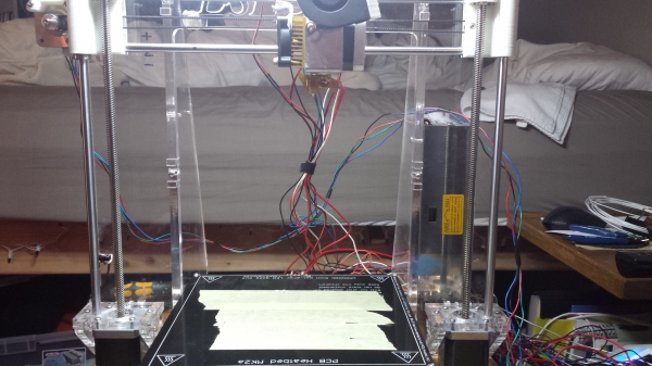
Well I got the board to work and has fluid motion on all axis, and I am trying to calibrate the steps/mm for the x-axis and it stops at 160mm and wont go any further. I have attached a picture and have adjusted my settings in config.h to no help. Is there a dimension I should be setting it to enable it to travel further? 
here is my mechanical settings as of now:
//===========================================================================
//=============================Mechanical Settings===========================
//===========================================================================
// Endstop Settings
#define ENDSTOPPULLUPS // Comment this out (using // at the start of the line) to disable the endstop pullup resistors
// The pullups are needed if you directly connect a mechanical endswitch between the signal and ground pins.
const bool X_ENDSTOPS_INVERTING = false; // set to true to invert the logic of the endstops.
const bool Y_ENDSTOPS_INVERTING = false; // set to true to invert the logic of the endstops.
const bool Z_ENDSTOPS_INVERTING = false; // set to true to invert the logic of the endstops.
// For Inverting Stepper Enable Pins (Active Low) use 0, Non Inverting (Active High) use 1
#define X_ENABLE_ON 0
#define Y_ENABLE_ON 0
#define Z_ENABLE_ON 0
#define E_ENABLE_ON 0 // For all extruders
// Disables axis when it's not being used.
#define DISABLE_X false
#define DISABLE_Y false
#define DISABLE_Z true
#define DISABLE_E false // For all extruders
#ifdef REPRAPPRO_MENDEL
#define AXES_MAX_LENGTHS {210, 210, 140}
#define INVERT_X_DIR false // for Mendel set to false, for Orca set to true
#define INVERT_Y_DIR true // for Mendel set to true, for Orca set to false
#define INVERT_Z_DIR false // for Mendel set to false, for Orca set to true
#define INVERT_E0_DIR true // for direct drive extruder v9 set to true, for geared extruder set to false
#define INVERT_E1_DIR true // for direct drive extruder v9 set to true, for geared extruder set to false
#define INVERT_E2_DIR true // for direct drive extruder v9 set to true, for geared extruder set to false
#endif
#ifdef REPRAPPRO_MENDEL2
#define AXES_MAX_LENGTHS {210, 210, 140}
#define INVERT_X_DIR false // for Mendel set to false, for Orca set to true
#define INVERT_Y_DIR true // for Mendel set to true, for Orca set to false
#define INVERT_Z_DIR false // for Mendel set to false, for Orca set to true
#define INVERT_E0_DIR true // for direct drive extruder v9 set to true, for geared extruder set to false
#define INVERT_E1_DIR true // for direct drive extruder v9 set to true, for geared extruder set to false
#define INVERT_E2_DIR true // for direct drive extruder v9 set to true, for geared extruder set to false
#endif
#ifdef REPRAPPRO_HUXLEY
#define AXES_MAX_LENGTHS {155, 150, 90}
#define INVERT_X_DIR false // for Mendel set to false, for Orca set to true
#define INVERT_Y_DIR false // for Mendel set to true, for Orca set to false
#define INVERT_Z_DIR false // for Mendel set to false, for Orca set to true
#define INVERT_E0_DIR true // for direct drive extruder v9 set to true, for geared extruder set to false
#define INVERT_E1_DIR true // for direct drive extruder v9 set to true, for geared extruder set to false
#define INVERT_E2_DIR true // for direct drive extruder v9 set to true, for geared extruder set to false
#endif
// ENDSTOP SETTINGS:
// Sets direction of endstops when homing; 1=MAX, -1=MIN
#define X_HOME_DIR -1
#define Y_HOME_DIR -1
#define Z_HOME_DIR -1
#define min_software_endstops false //If true, axis won't move to coordinates less than zero.
#define max_software_endstops true //If true, axis won't move to coordinates greater than the defined lengths below.
// The position of the homing switches. Use MAX_LENGTH * -0.5 if the center should be 0, 0, 0
#define X_HOME_POS 0
#define Y_HOME_POS 0
#define Z_HOME_POS 0
//// MOVEMENT SETTINGS
#define NUM_AXIS 4 // The axis order in all axis related arrays is X, Y, Z, E
/*
We've shipped a number of different configurations of belt and pulley now, so probably need some ifdef statements! At the moment, they all get the same.
White polyurethane belt (T2.5), 14-tooth printed pulley: 91.4286 step per mm (Original Huxley, Legacy Mendel)
Black rubber belt (MXL), 17-tooth printed pulley: 92.635 step per mm (Huxley, Mendel Mono and Tri since 1/4/2013)
Black rubber belt (MXL), 18-tooth aluminium pulley: 87.489 step per mm (Huxley, Mendel Mono and Tri since 1/1/2014)
Also, two different extruders:
Original eMaker/RepRapPro-style: 920 steps per mm (Original Huxley, Legacy Mendel)
New version (NEMA14 and NEMA17): 660 steps per mm (Huxley, Mendel Mono and Tricolour since 1/4/2013)
*/
#ifdef REPRAPPRO_MENDEL2
#define X_MAX_LENGTH 210
#define Y_MAX_LENGTH 210
#define Z_MAX_LENGTH 180
#define HOMING_FEEDRATE {10*60, 10*60, 1*60, 0} // set the homing speeds (mm/min)
#define FAST_HOME_FEEDRATE {50*60, 50*60, 1*60, 0} // set the homing speeds (mm/min)
#define DEFAULT_MAX_FEEDRATE {500, 500, 3, 45}
#define DEFAULT_MAX_FEEDRATE {300, 300, 3, 45} // (mm/sec)
#define DEFAULT_MAX_ACCELERATION {800,800,30,250} // X, Y, Z, E maximum start speed for accelerated moves. E default values
// X, Y, Z, E steps per mm
#define DEFAULT_AXIS_STEPS_PER_UNIT {100, 87.489, 4000, 660.0} // <- 16-tooth aluminium pulley
//#define DEFAULT_AXIS_STEPS_PER_UNIT {92.635, 92.635, 4000, 660} // <- 17-tooth printed pulley
#endif
// Defaults changed by the G10 command
#define X_EXTRUDER_OFFSET 0
#define Y_EXTRUDER_OFFSET 0
#define Z_EXTRUDER_OFFSET 0
#define STANDBY_TEMP 140
#define PLA_TEMP 205
#define ABS_TEMP 250
#define DEFAULT_TEMP PLA_TEMP
#define DEFAULT_ACCELERATION 1000 // X, Y, Z and E max acceleration in mm/s^2 for printing moves
#define DEFAULT_RETRACT_ACCELERATION 1000 // X, Y, Z and E max acceleration in mm/s^2 for r retracts
//
#define DEFAULT_XYJERK 15.0 // (mm/sec)
#define DEFAULT_ZJERK 0.4 // (mm/sec)
#define DEFAULT_EJERK 15.0 // (mm/sec)
Edited 1 time(s). Last edit at 12/12/2014 10:23PM by Andreasv007.
|
Re: Help With Prusa i3 Calibration December 13, 2014 02:22AM |
Registered: 10 years ago Posts: 581 |
You're using the reprappro version of Marlin, which is specifically modified to support reprappro's mendel or huxley printers, not the prusa i3.
If your travel is limited to about 160mm in the x or y directions, your firmware has been configured for the huxley, which has a small build platform.
1. Check at the top of the file configuration.h for the type of printer you have defined:
// Uncomment ONE of the next three lines - the one for your RepRap machine
//#define REPRAPPRO_HUXLEY
//#define REPRAPPRO_MENDEL //Legacy Mendel
//#define REPRAPPRO_MENDEL2 // Mono Mendel
// Uncomment ONE of the next two lines - the one for your master controller electronics
//#define REPRAPPRO_MELZI
//#define REPRAPPRO_SANGUINOLOLU
If REPRAPPRO_HUXLEY is uncommented, that is the source of your travel issues (and more than likely a lot of other issues).
2. Consider using Marlin firmware from github instead - it has support for the Prusa i3 with a Melzi board [github.com]. It will make your life much simpler.
[3DKarma.com] - suppliers of quality, affordable 3D printer kits and filament for the UK market.
|
Re: Help With Prusa i3 Calibration December 15, 2014 12:46PM |
Registered: 9 years ago Posts: 6 |
3DKarma,
Thank you VERY MUCH for leading me to that firmware. It made all the difference in the world!!!!
I am now running into a problem of my Z-axis now moving past my limit switch at the bottom as if it doesn't realize its there. I've checked with a multimeter to see if it functions properly and its hooked up appropriately. possibly a height setting in config.h?
I think after that I am going to be ready for a print!
thanks again, It really did make life much easier for me!
|
Re: Help With Prusa i3 Calibration December 15, 2014 01:42PM |
Registered: 10 years ago Posts: 581 |
No probs, Andreas.
Send M119 to the printer and it will report your endstop status. Trigger the Z axis manually and send M119 again to see what you get. There isn't a height setting in configuration.h for this, but there are settings for max and min endstops, pullup resistors and inverting the endstops. These need to be correct before it'll all work.
If you're still having problems after this, post your M119 results and your configuration.h here.
[3DKarma.com] - suppliers of quality, affordable 3D printer kits and filament for the UK market.
|
Re: Help With Prusa i3 Calibration December 17, 2014 10:24AM |
Registered: 9 years ago Posts: 6 |
I got everything to work as needed and I have full control and even did a dry run last night! very exciting!!
your help was invaluable, I had to invert my end-stops to open instead of triggered and everything was perfect and no more issues.
I have one last question, and maybe it is also a simple answer:
The temp keeps swinging up and down and not averaging out, and the print wont start until it has solid temp. Is there a setting I can change to set the temps to help it stable out and not fluctuate so high? or perhaps my thermistor is not secured close enough to the hot-end that it is not receiving a proper reading?
other than that everything works beautifully, I couldn't be happier
your the man 3DKarma!
|
Re: Help With Prusa i3 Calibration December 17, 2014 11:43AM |
Registered: 10 years ago Posts: 581 |
Glad I could help.
Marlin has support for auto-tuning the PID settings of your printer to give a good, stable temperature. There's a good write-up of the procedure at the reprap wiki. [reprap.org]
[3DKarma.com] - suppliers of quality, affordable 3D printer kits and filament for the UK market.
Marlin has support for auto-tuning the PID settings of your printer to give a good, stable temperature. There's a good write-up of the procedure at the reprap wiki. [reprap.org]
[3DKarma.com] - suppliers of quality, affordable 3D printer kits and filament for the UK market.
Sorry, only registered users may post in this forum.