Home
>
Developers
>
Topic
Torqspline XY Axis Block Assembly
Posted by Iceman086
|
Torqspline XY Axis Block Assembly September 13, 2011 09:00AM |
Registered: 13 years ago Posts: 70 |
The Following Post Is Picture Heavy!!!!
I am planning on using Torqspline Screw Rods for linear motion on my X and Y axis. I have been looking around and designing parts and here is what I have come up with.
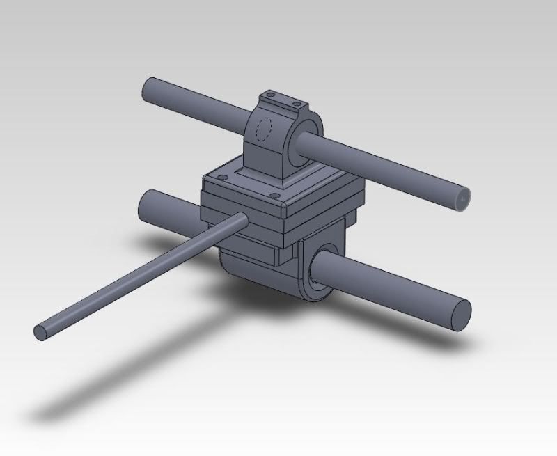
This is a picture of the final assembly, unfortunatly is is upside down in solidworks. But I threw this all together and I haven't had time to correct this yet. The parts in the picture below were all modeled by me. The bottom piece is a pillow block from McMaster Carr (PN: 1052k11) that I modeled based off of the dimensions in the online catalog. The other parts are all custom designs that will be printed using a friends Makerbot.
The two parallel rods a the Torqspline Screw (top rod) and the smooth Guide/Support rod (bottom rod). The rod on the far left is the Axis Rod. It will connect to a similar assembly on the opposite side of the printer to allow movement along the axis. Because a gantry system is being used, 2 assembly's like the one above will move along the X and Y planes. Where the Axis Rods over lap is where the extruder head will be positioned.
Torqspline Screw: 3/8" Dia.
Guide/Support Rod: 1/2" Dia.
(Total Height of the assembly is roughly 3.15 in; Center point of Screw to Center point of Guide Rod: Approx 2 in)
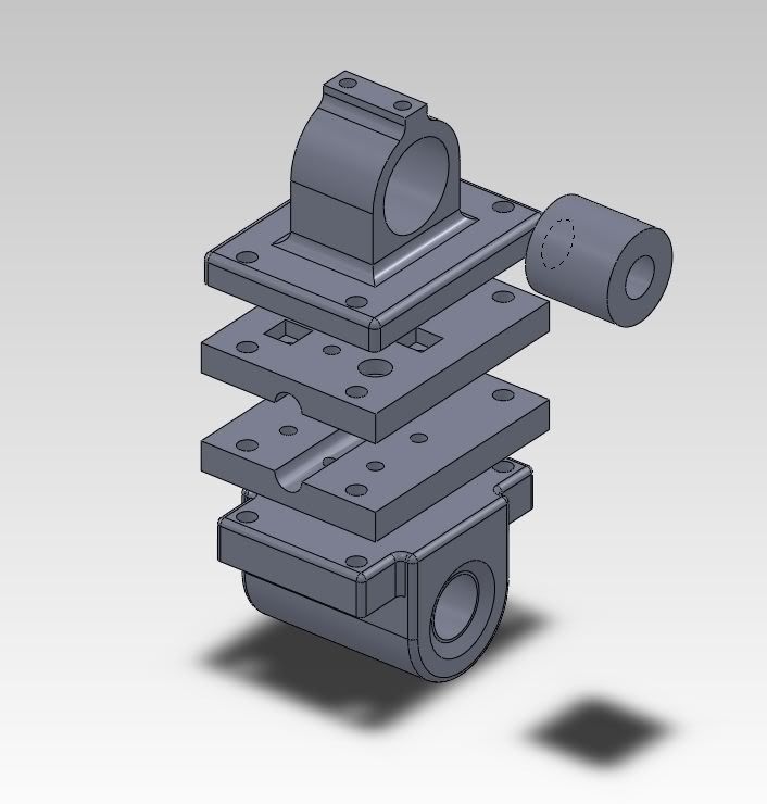
Here is an exploded view of all of the parts together.
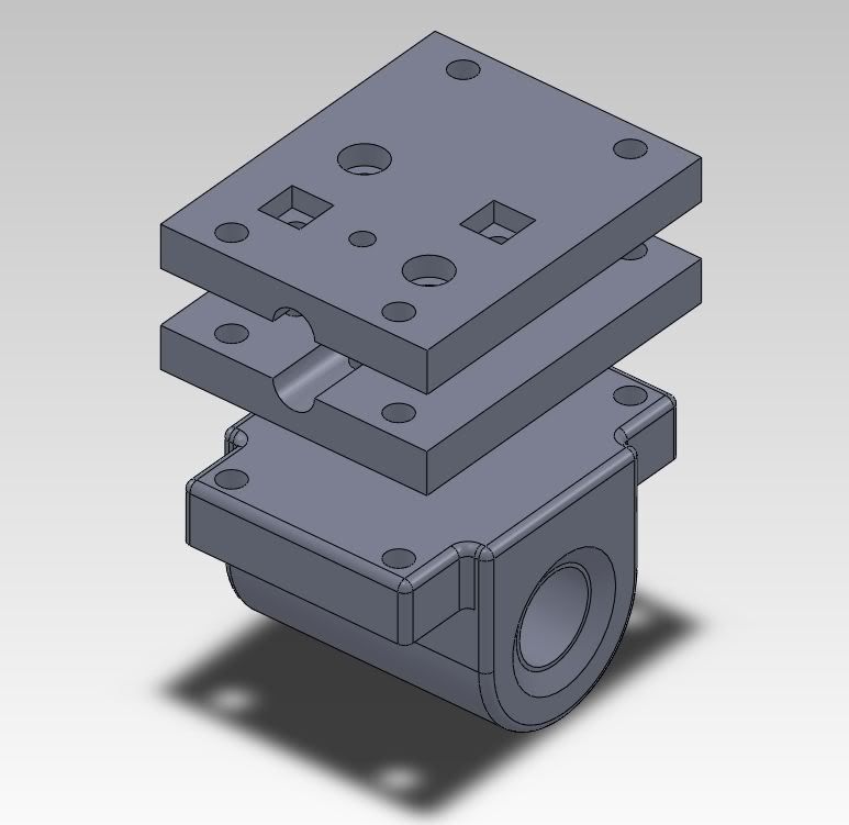
Here you can see the top side of the Axis plate. The 4 counter bore holes, which are circular and square, are for screws and square nuts to nest inside of. These counter bore hole will help to secure the axis rod in place. The small hole in the center of the counter bores is meant for a set screw which is optional but may be needed.
Here is another view of the Axis Rod Plate with only the bottom plate and the McMaster Carr "Pillow Block".
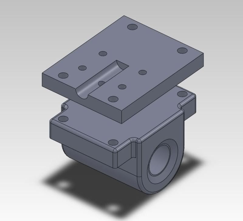
Eventually I may end up combining the top and bottom Axis Rod Plates to create one solid block, but for now I like the concept of being able to secure the Axis Rod in multiple ways.
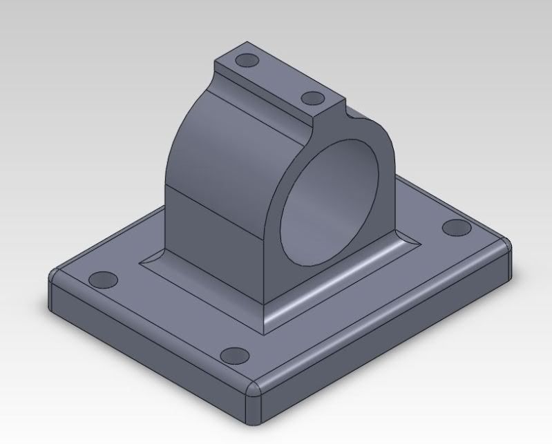
Here is the Motion Flange (my name for the part) that will have the Screw Sleeve placed inside of it. The Motion Flange will restrict the screw sleeve from spinning which in turn creates linear motion when the Screw rotates. The two holes on the top of the Flange are for set screws that will secure the Screw Sleeve in place.
If anyone has any thoughts, suggestions or questions please let me know! I posted this here to get input on the design to see if anyone feels that there are or will be issues with the way that this is all designed.
I am planning on using Torqspline Screw Rods for linear motion on my X and Y axis. I have been looking around and designing parts and here is what I have come up with.
This is a picture of the final assembly, unfortunatly is is upside down in solidworks. But I threw this all together and I haven't had time to correct this yet. The parts in the picture below were all modeled by me. The bottom piece is a pillow block from McMaster Carr (PN: 1052k11) that I modeled based off of the dimensions in the online catalog. The other parts are all custom designs that will be printed using a friends Makerbot.
The two parallel rods a the Torqspline Screw (top rod) and the smooth Guide/Support rod (bottom rod). The rod on the far left is the Axis Rod. It will connect to a similar assembly on the opposite side of the printer to allow movement along the axis. Because a gantry system is being used, 2 assembly's like the one above will move along the X and Y planes. Where the Axis Rods over lap is where the extruder head will be positioned.
Torqspline Screw: 3/8" Dia.
Guide/Support Rod: 1/2" Dia.
(Total Height of the assembly is roughly 3.15 in; Center point of Screw to Center point of Guide Rod: Approx 2 in)

Here is an exploded view of all of the parts together.

Here you can see the top side of the Axis plate. The 4 counter bore holes, which are circular and square, are for screws and square nuts to nest inside of. These counter bore hole will help to secure the axis rod in place. The small hole in the center of the counter bores is meant for a set screw which is optional but may be needed.

Here is another view of the Axis Rod Plate with only the bottom plate and the McMaster Carr "Pillow Block".

Eventually I may end up combining the top and bottom Axis Rod Plates to create one solid block, but for now I like the concept of being able to secure the Axis Rod in multiple ways.
Here is the Motion Flange (my name for the part) that will have the Screw Sleeve placed inside of it. The Motion Flange will restrict the screw sleeve from spinning which in turn creates linear motion when the Screw rotates. The two holes on the top of the Flange are for set screws that will secure the Screw Sleeve in place.

If anyone has any thoughts, suggestions or questions please let me know! I posted this here to get input on the design to see if anyone feels that there are or will be issues with the way that this is all designed.
|
Re: Torqspline XY Axis Block Assembly September 15, 2011 10:56PM |
Registered: 13 years ago Posts: 70 |
|
Re: Torqspline XY Axis Block Assembly September 19, 2011 11:18PM |
Registered: 13 years ago Posts: 581 |
|
Re: Torqspline XY Axis Block Assembly September 20, 2011 03:41AM |
Registered: 13 years ago Posts: 70 |
I did think about using belts in the original design that I had for the printer. The problem became a matter of "where can I find belts that are 84" long?" then it was, "can a belt of that size do a continuous run for up to 48 hours on large scale prints?" Even if the belts are tightened regularly, over a distance like that with no tensioning wheel (though one could be added to the design) running for long periods, I just wasn't sure if I could trust them.
I am sure that there are belts out there that would work with this design, but I just haven't come across them.
If the rods fail then I am still willing to use belts, but I want to try using something a bit different that *hopefully* will be able to give me a high quality print quicker than acme or lead screws that have been used in some of the other large scale printers.
Thanks commenting!!!
|
Re: Torqspline XY Axis Block Assembly September 20, 2011 06:59AM |
Registered: 13 years ago Posts: 7,616 |
Iceman, I think you simply have to build this stuff. There are literally thousands of detail designs open for discussion out there, so you can't really expect to get a detailed review of every one.
A rule of thumb is: "It Works!" ist _the_ single important feature a design can achieve in the RepRap world. To demonstrate that, you simply have to build a design. Not that difficult if you have a printer yourself or a friend with one.
A rule of thumb is: "It Works!" ist _the_ single important feature a design can achieve in the RepRap world. To demonstrate that, you simply have to build a design. Not that difficult if you have a printer yourself or a friend with one.
| Generation 7 Electronics | Teacup Firmware | RepRap DIY |
|
Re: Torqspline XY Axis Block Assembly September 20, 2011 12:47PM |
Registered: 13 years ago Posts: 70 |
|
Re: Torqspline XY Axis Block Assembly September 23, 2011 03:25PM |
Registered: 14 years ago Posts: 73 |
|
Re: Torqspline XY Axis Block Assembly September 24, 2011 05:03PM |
Registered: 13 years ago Posts: 70 |
With a rack and pinion system the gear moving the axis rods along the XY plane which means that the motor would have to move with the axis rod. That means that there is more weight moving along the axis which means more momentum. I want to try to keep the parts moving the axis rods as light as possible to keep backlash and extra movement to a minimum.
I considered using a rack and pinion system for the Z axis platform but I decided to stick with acme screws there as well to keep from adding more weight to that axis point as well. Though I might reconsider if I can find some that fall within my budget.
I considered using a rack and pinion system for the Z axis platform but I decided to stick with acme screws there as well to keep from adding more weight to that axis point as well. Though I might reconsider if I can find some that fall within my budget.
Sorry, only registered users may post in this forum.