PSU Wiring Help
Posted by academicdave
|
PSU Wiring Help January 17, 2014 09:30AM |
Registered: 10 years ago Posts: 51 |
Managed to get everything built except for the wiring and PSU, that's the last step. Being in America I had to separately source the PSU. I bought this one based on a recommendation in the forum. But when I pull it out the wires don't match the build instructions in nopheads plans. There appears to be a lot of extra wires. Six separate bundles coming out from the PSU. Is there a more detailed wiring diagram somewhere that isn't based on the colors of the Alpine? Or would it be easier if I just ordered the Alpine off ebay and waited. Sorry I might be asking a stupid question here, new to the electrical stuff here, but it just appears to me that the coolmax has extra connectors coming out of it compared to the alpine.
|
Re: PSU Wiring Help January 17, 2014 10:49AM |
Registered: 10 years ago Posts: 541 |
If you can post an image showing the power connectors then we can tell you what should go where.
Regards,
Neil Darlow
I try to write with consideration for all nationalities. Please let me know if something is unclear.
Printing with Mendel90 from fedora 25 using Cura, FreeCAD, MeshLab, OpenSCAD, Skeinforge and Slic3r tools.
Regards,
Neil Darlow
I try to write with consideration for all nationalities. Please let me know if something is unclear.
Printing with Mendel90 from fedora 25 using Cura, FreeCAD, MeshLab, OpenSCAD, Skeinforge and Slic3r tools.
|
Re: PSU Wiring Help January 17, 2014 11:44AM |
Registered: 10 years ago Posts: 51 |
|
Re: PSU Wiring Help January 17, 2014 12:59PM |
Admin Registered: 17 years ago Posts: 7,879 |
All ATX PSU wires should be standard colours that match the instructions, they are not specific to the Alpine. The only exception I know of is the 3.3V sense wire is sometimes a thin orange wire rather than brown, but it can be identified because it goes in the same pin of the big connector as one of the orange.
The numbers of each wire tends to vary and gauge of the wire. Basically use as many of the yellow and black as you can get into the connector and insulate the unused ones.
If you buy the Alpine you linked on eBay from the UK it won't work in the US unless you modify it for 110V. That involves fitting a wire to act as a jumper on the PCB where a switch would be connected.
[www.hydraraptor.blogspot.com]
|
Re: PSU Wiring Help January 17, 2014 01:10PM |
Registered: 10 years ago Posts: 51 |
|
Re: PSU Wiring Help January 17, 2014 07:55PM |
Registered: 10 years ago Posts: 51 |
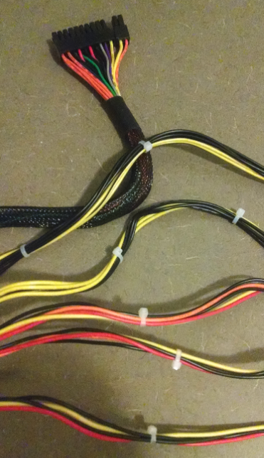
So the PSU has six bundles of wires. As you can see below in the photo.
The first bundle which has various colors. 23 wires in all.
Second Bundle 2-blacks, 2-yellows.
Third Bundle 3-yellows, 3-blacks,
Fourth Orange, 2- Black, Red, Yellow,
Fifth Yellow, 2-Black, Red,
Six Yellow, 2-black, Red
So if think I might have two extra bundles, giving me extra, red, black, yellow wires?
Here are links to high resolution photos if that helps.
[dl.dropboxusercontent.com]
[dl.dropboxusercontent.com]
Edited 1 time(s). Last edit at 01/17/2014 11:17PM by academicdave.
|
Re: PSU Wiring Help January 18, 2014 04:46AM |
Registered: 10 years ago Posts: 541 |
I think you can manage with the information nophead provided earlier.
The only issue would be the sense wire colour which is brown here in the UK and may be orange on yours. You should be able to determine which one it is.
Regards,
Neil Darlow
I try to write with consideration for all nationalities. Please let me know if something is unclear.
Printing with Mendel90 from fedora 25 using Cura, FreeCAD, MeshLab, OpenSCAD, Skeinforge and Slic3r tools.
|
Re: PSU Wiring Help January 18, 2014 05:11AM |
Admin Registered: 17 years ago Posts: 7,879 |
The bundling is irrelevant. All the wires of the same colour are connected together inside the PSU. The colours appear to be exactly the same as the instructions, including the brown.
[www.hydraraptor.blogspot.com]
[www.hydraraptor.blogspot.com]
|
Re: PSU Wiring Help January 18, 2014 09:22AM |
Registered: 10 years ago Posts: 51 |
|
Re: PSU Wiring Help January 18, 2014 11:24AM |
Admin Registered: 17 years ago Posts: 7,879 |
It will make no difference electrically if you solder them together or not. I would just bundle the un-stripped wires and insulate them.
[www.hydraraptor.blogspot.com]
[www.hydraraptor.blogspot.com]
|
Re: PSU Wiring Help January 30, 2014 02:39AM |
Registered: 10 years ago Posts: 94 |
Hi guys,
I was just wondering if there are any alternatives (possibly cheaper ) to getting the aluminum clad resistors ?
also would it be alright Nophead to cut the extra wires of at the board - I have seen many people on youtube do that to save the insulation -
- thank you so much for all of the amazing work you have done/are doing with the mendel90 design !!!!!!
thanks
Jeremy
I was just wondering if there are any alternatives (possibly cheaper
) to getting the aluminum clad resistors ? also would it be alright Nophead to cut the extra wires of at the board - I have seen many people on youtube do that to save the insulation -
- thank you so much for all of the amazing work you have done/are doing with the mendel90 design !!!!!!
thanks
Jeremy
|
Re: PSU Wiring Help January 30, 2014 07:30AM |
Admin Registered: 17 years ago Posts: 7,879 |
The power dissipation is only 2.5W and 2.3W, so you could use 3W ceramic resistors but they will get very hot (dangerous to touch). Normally you would mount them on a PCB with long leads and perhaps ceramic standoffs inside an enclosure. I use the 15W AL clad because they are safe to touch and self supporting.
You could possible also use 12V car light bulbs but it is hard to calculate the wattage as the resistance of a bulb is highly non-linear.
Yes you can cut the wires at the board but I don't advise the general public to open the PSU for safety reasons.
[www.hydraraptor.blogspot.com]
You could possible also use 12V car light bulbs but it is hard to calculate the wattage as the resistance of a bulb is highly non-linear.
Yes you can cut the wires at the board but I don't advise the general public to open the PSU for safety reasons.
[www.hydraraptor.blogspot.com]
|
Re: PSU Wiring Help January 30, 2014 08:45AM |
Registered: 10 years ago Posts: 94 |
|
Re: PSU Wiring Help January 30, 2014 11:32AM |
Admin Registered: 17 years ago Posts: 7,879 |
It will be neater. Electrically it will make no difference if the total copper area is the same.
It might be hard to attach a bigger gauge wire to the PCB inside the PSU. Some have lots of small holes. Others group them in bundles into larger holes, sometimes using a ferrule.
[www.hydraraptor.blogspot.com]
It might be hard to attach a bigger gauge wire to the PCB inside the PSU. Some have lots of small holes. Others group them in bundles into larger holes, sometimes using a ferrule.
[www.hydraraptor.blogspot.com]
|
Re: PSU Wiring Help January 31, 2014 08:13AM |
Registered: 10 years ago Posts: 94 |
|
Re: PSU Wiring Help January 31, 2014 09:53AM |
Registered: 10 years ago Posts: 869 |
It really depends on the design of the supply. Some work fine. Some don't. It can be hard on the supply though as the rails may be regulated separately.Quote
Jerms.a320
Is it alright to use a combination of 12v - 1 and 12v - 2 lines together ? - my power supply is/was modular (I got it free from a friend) and I have only 5 full length 12v 1 wires
Which electronics are you using? Melzi I beleive has just a single power input so you'd have to try to combine them what that supply if either rail couldn't provide enough by itself. Other electronics, e.g. RAMPS 1.4, have separate inputs, one for just the bed since it takes the most, and the rest powered by the other. In those cases you could just keep the rails separate.
|
Re: PSU Wiring Help January 31, 2014 10:30AM |
Admin Registered: 17 years ago Posts: 7,879 |
All the PSU schematics I have seen use one converter for 12V and split the rails with separate current sense resistors. You could test this by measuring the resistance between the two 12V rails. If it is only a small fraction of an Ohm then it is a single rail split so there should be no problem combining them.
You can allocate one rail to the Melzi and the other to the bed simply by connecting the bed's positive feed direct to the PSU +12V, rather than the bed + terminal on the Melzi.
[www.hydraraptor.blogspot.com]
You can allocate one rail to the Melzi and the other to the bed simply by connecting the bed's positive feed direct to the PSU +12V, rather than the bed + terminal on the Melzi.
[www.hydraraptor.blogspot.com]
|
Re: PSU Wiring Help January 31, 2014 10:55AM |
Registered: 10 years ago Posts: 94 |
On my PSU there are only 4 wires coming off the second "rail", and 8 from the first rail
I am using RAMPS 1.4 , I had a crack at measuring the resistance between the rails and got 0.00 Ohms
- should I just use 6 wires to the two inputs on the RAMPS board ?
Nophead, I was just wondering why the green wire and the black are connected via the 4R7 resistor to the sense and orange wire, I haven't seen any people on youtube do that (I know its not that great a source ) ?
thanks
|
Re: PSU Wiring Help January 31, 2014 01:53PM |
Registered: 10 years ago Posts: 869 |
I'd just split them, one rail to one set of inputs, the other rail to the other set of inputs. I wouldn't get too caught up in the number of wires for each rail.Quote
Jerms.a320
On my PSU there are only 4 wires coming off the second "rail", and 8 from the first rail
I am using RAMPS 1.4 , I had a crack at measuring the resistance between the rails and got 0.00 Ohms
- should I just use 6 wires to the two inputs on the RAMPS board ?
Some power supplies require a load on the 3.3v and/or 5v rail in order to properly regulate the 12v. Your supply may or may not need this, but it's not going to hurt if it does not.Quote
I was just wondering why the green wire and the black are connected via the 4R7 resistor to the sense and orange wire, I haven't seen any people on youtube do that (I know its not that great a source ) ?
|
Re: PSU Wiring Help January 31, 2014 02:45PM |
Admin Registered: 17 years ago Posts: 7,879 |
The green needs to be connected to ground to switch the PSU on. Joining it at the resistor is just a convenient way of doing that without wasting another black wire.
The brown sense wire was connected to one of the orange wires at the 24 way connector, which has been cut off, so needs to be re-connected to one of the orange wires. Again doing it at the resistor is the most convenient place.
I would connect as many of the yellow wires as you can get into the connectors. That minimises the voltage drop in the wiring and allows the bed to heat a bit faster.
[www.hydraraptor.blogspot.com]
|
Re: PSU Wiring Help January 31, 2014 06:38PM |
Registered: 10 years ago Posts: 94 |
Ok, so the 2nd resistor , will also be a load on the 3.3v rail, that could possibly help regulate the 12v ...... I've attached the 1st resister to the 5v and ground
would it be better to use more of the yellow wires for the heated bed ( I could take the 4 from the 2nd rail for the RAMPS and the 8 from the 1st rail to the heated bed ) ?
Is it safe to measure the voltage between the ground and the two 12v rails (obviously while the PSU is running) ?
Thanks so much for the help guys
|
Re: PSU Wiring Help February 01, 2014 05:16AM |
Admin Registered: 17 years ago Posts: 7,879 |
As I said before, more wires are better. The cheap PSUs I use have very thin wires but more expensive ones use bigger gauge, so it has less effect using more of them.
Yes it is safe to measure voltage provided your meter is set to voltage and you don't cause a short with the probes.
[www.hydraraptor.blogspot.com]
Yes it is safe to measure voltage provided your meter is set to voltage and you don't cause a short with the probes.
[www.hydraraptor.blogspot.com]
|
Re: PSU Wiring Help February 01, 2014 07:28AM |
Registered: 10 years ago Posts: 94 |
Sorry, only registered users may post in this forum.