Interpreting a test print
Posted by Arakon
|
Interpreting a test print October 26, 2014 04:17PM |
Registered: 9 years ago Posts: 157 |
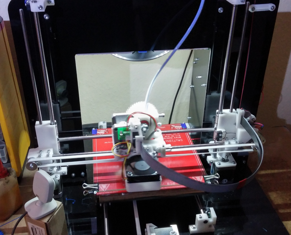
I recently finished my Mendel90.
I just printed one of the basic test objects, sliced with Cura and printed from SD. Same issues remain if sliced with slic3r or simplify3d
Can anyone tell me what settings affect the issues in the pictures? Half shiny, half not, messed up head section, loose threads..
The biggest one is the bottom, the lines are round and not connected, and there's hardly any adhesion going on. I am using the filament that came with the printer (faberdashy), in the case of this print, it was done at 200°, 70° bed, 0.4mm first layer, 0.2mm layer height. I re-adjusted the Z home point several times (it's at 204.3 mm for me) and leveled the bed several times too. The nozzle is now at a height where a sheet of normal paper will fit under it with a just noticable (feeling and sound) scratching.
Edited 1 time(s). Last edit at 10/26/2014 04:20PM by Arakon.
|
Re: Interpreting a test print October 26, 2014 05:08PM |
Registered: 10 years ago Posts: 541 |
A few notes that might help:
1) The Faberdashery Village Green filament supplied with the Kit prints well at 185C. No need to go higher.
2) A first layer height of 0.4mm is too high. Print all layers at the same height e.g. 0.2mm.
3) Recover the skirt printed around your object and measure its height at several places and use the average measurement to adjust your Z height.
4) Clean your glass with Pure White Vinegar which you can purchase at any supermarket. Just wipe the surface with a folded tissue dampened with the vinegar until it squeaks.
Proper Z height is very important for getting PLA to adhere to plain glass. The use of vinegar and adjustment of Z height based on a measured skirt greatly helps this.
Regards,
Neil Darlow
I try to write with consideration for all nationalities. Please let me know if something is unclear.
Printing with Mendel90 from fedora 25 using Cura, FreeCAD, MeshLab, OpenSCAD, Skeinforge and Slic3r tools.
|
Re: Interpreting a test print October 26, 2014 05:32PM |
Registered: 9 years ago Posts: 157 |
1) I had only tried higher to see if that would help, actually.
3) Did that, I get an average of 0.28mm now after another adjustment. Is that good enough? I'm not sure I can actually adjust it any finer in the firmware?
4) I use brake cleaner.. that gets rid of any trace of grease or anything.
I'm currently doing another print after an email from nophead with adjusted settings and using skeinforge, it stuck to the board right away at least.
Thanks for the help.
|
Re: Interpreting a test print October 26, 2014 05:49PM |
Admin Registered: 17 years ago Posts: 7,879 |
0.28mm for a 0.3mm layer is near enough but you can adjust it to the resolution of the motors or a floating point number, which ever is higher (should be the motors at 0.0003125mm) in the firmware. It tends to vary a bit when the machine is new as things bed in.
Note that the fan should be on after the first layer for PLA if you are using other slicers.
[www.hydraraptor.blogspot.com]
Note that the fan should be on after the first layer for PLA if you are using other slicers.
[www.hydraraptor.blogspot.com]
|
Re: Interpreting a test print October 26, 2014 06:08PM |
Registered: 9 years ago Posts: 157 |
Update on this.. new Z-height and sliced with skeinforge and nophead's settings greatly improved it, but there's still some oddness.. especially the stray threads of PLA on the new print, and still some partial shininess.. what causes that?
|
Re: Interpreting a test print October 26, 2014 08:11PM |
Admin Registered: 17 years ago Posts: 7,879 |
I think the stray threads are due to the outline starting in mid air due to the extreme overhang, so they just fall down. Skeinforge sometimes does that on complicated shapes with overhangs.
I don't know what would created the shiny / matt areas on the same print. Usually higher temperatures and thicker layers are more shiny than lower temperature and thinner layers.
[www.hydraraptor.blogspot.com]
I don't know what would created the shiny / matt areas on the same print. Usually higher temperatures and thicker layers are more shiny than lower temperature and thinner layers.
[www.hydraraptor.blogspot.com]
|
Re: Interpreting a test print October 30, 2014 06:22PM |
Registered: 9 years ago Posts: 157 |
Got it calibrated further with a dial gauge, thanks.
I switched to a different filament now (3mm blue PLA by Trijexx).
Using the same settings as before (with adjustments for the filament thickness of course), I now get okay prints with it, but still some issues.
The first image shows bumps in the first layer that randomly follow the outline. The same occured with an ABS sample I tried.
The next one shows the exact same settings, again bumps around the bottom layer, but the rest looks quite smooth.
The last one was done with the Z_home_pos raised by 0.1mm to see if the distance was the issue. The layer is still a bit wider than the following ones, but no blobs. However, instead the layers don't always seem to connect right.
Any suggestions on which options to experiment with?
Also, I measured the skirt before. It was at ~0.17 mm. I lowered the z_home_pos by 0.1 (204.5 to 204.4) and now the skirt is 0.15mm.. shouldn't it be thicker now? *edit*
I tried 204.3 now and still get a thickness of 0.15. I'm confused?
Edit 2: 204.2 now and now the layer is 0.23-0.29 thick. Should I adjust the bed to be a little higher?
Edited 4 time(s). Last edit at 10/30/2014 07:21PM by Arakon.
I switched to a different filament now (3mm blue PLA by Trijexx).
Using the same settings as before (with adjustments for the filament thickness of course), I now get okay prints with it, but still some issues.
The first image shows bumps in the first layer that randomly follow the outline. The same occured with an ABS sample I tried.

The next one shows the exact same settings, again bumps around the bottom layer, but the rest looks quite smooth.

The last one was done with the Z_home_pos raised by 0.1mm to see if the distance was the issue. The layer is still a bit wider than the following ones, but no blobs. However, instead the layers don't always seem to connect right.

Any suggestions on which options to experiment with?
Also, I measured the skirt before. It was at ~0.17 mm. I lowered the z_home_pos by 0.1 (204.5 to 204.4) and now the skirt is 0.15mm.. shouldn't it be thicker now? *edit*
I tried 204.3 now and still get a thickness of 0.15. I'm confused?
Edit 2: 204.2 now and now the layer is 0.23-0.29 thick. Should I adjust the bed to be a little higher?
Edited 4 time(s). Last edit at 10/30/2014 07:21PM by Arakon.
|
Re: Interpreting a test print October 31, 2014 07:19AM |
Admin Registered: 17 years ago Posts: 7,879 |
If it is not laying down perfectly aligned walls then either the nozzle is wandering due to something being loose or the filament flow is irregular.
Is the nozzle firmly attached to the Wade's block? Is the extruder firmly attached to the carriage? Are the belts tight? Are both X ends resting on their nuts?
Something seems to have got worse since you switched filaments. Is the hobbed bolt gripping the filament or is it slipping? Is it consistent diameter and round, not oval? Does it feed easily by hand? If not it may need a higher temperature.
[www.hydraraptor.blogspot.com]
|
Re: Interpreting a test print October 31, 2014 07:33AM |
Registered: 10 years ago Posts: 541 |
Increasing Z_HOME_POS should reduce layer height and vice versa.
The value of Z_HOME_POS largely depends on where you set the X-carriage height before you start the bed levelling procedure. I place the temporary washers under the front bed pillars and measure the bed height there before adjusting the Z-screws to a similar height. This has given me a Z_HOME_POS of 203.92 after final skirt measurement.
If you set the Z-screws too high before levelling you find that you have to raise the front of the bed significantly by adjusting the pillars. I try to minimise the amount of adjustment needed there.
Once you have your bed levelled, make sure E_STEPS_PER_MM is set correctly. I have found that this value can vary with temperature so you want to calibrate this at the required extrusion temperature. Use a calliper to measure this because you are working to 0.1mm resolution.
Looking at your photographs it looks, to me, that you just need to get consistent extrusion (E_STEPS_PER_MM) to maintain a good layer height.
Try to avoid the temptation to fiddle with parameters to create a good print. The calibration procedure should get you near to correct and readjustment of Z_HOME_POS from a skirt measurement should achieve higher quality. The rest is just down to material quality, optimal slicing, and correct operating temperatures.
Regards,
Neil Darlow
I try to write with consideration for all nationalities. Please let me know if something is unclear.
Printing with Mendel90 from fedora 25 using Cura, FreeCAD, MeshLab, OpenSCAD, Skeinforge and Slic3r tools.
|
Re: Interpreting a test print October 31, 2014 07:46AM |
Registered: 9 years ago Posts: 157 |
The E-steps are fine, it actually extrudes 100mm when I tell it to. What I wasn't aware of is that z_home may have values of 2 digits after the period, I believe I can home it in even closer this way. I started a print earlier and hope this comes out better, I increased the temperature by 5 degrees.
Everything is attached firmly now, although it did drop the big M8 nuts during the TARDIS print. I attached them more firmly now and with a small drop of loctite.
My right lead screw is not spinning straight, so I will try to get that set properly on the weekend too.
Everything is attached firmly now, although it did drop the big M8 nuts during the TARDIS print. I attached them more firmly now and with a small drop of loctite.
My right lead screw is not spinning straight, so I will try to get that set properly on the weekend too.
|
Re: Interpreting a test print October 31, 2014 10:00AM |
Admin Registered: 17 years ago Posts: 7,879 |
The M8 nuts should be tightened against each other with the star washer in between. That is enough to prevent them coming loose. I wouldn't use loctite because you might want to undo them to clean the hobbed bolt if you have a filament jam, or to replace the gears.
I don't think an off centre lead screw would give such bad results, perhaps a loose hobbed bolt could but I have found it to work quite well without nuts for PLA but not ABS.
If the filament has ever slipped it can leave chunks in the teeth of the hobbed bolt which can make the feed inconsistent until it is cleaned.
Sorry Neil, I don't understand what you are saying here. The bed should be levelled before Z_HOME_POS is calibrated. After that it is determined by the nozzle length, exact position of the top Z bracket, etc. It doesn't depend on where the X carriage was when you levelled the bed. The back two pillars should always be tight against the washers, only the front two are adjusted to get it level front to back.
[www.hydraraptor.blogspot.com]
I don't think an off centre lead screw would give such bad results, perhaps a loose hobbed bolt could but I have found it to work quite well without nuts for PLA but not ABS.
If the filament has ever slipped it can leave chunks in the teeth of the hobbed bolt which can make the feed inconsistent until it is cleaned.
Quote
The value of Z_HOME_POS largely depends on where you set the X-carriage height before you start the bed levelling procedure. I place the temporary washers under the front bed pillars and measure the bed height there before adjusting the Z-screws to a similar height. This has given me a Z_HOME_POS of 203.92 after final skirt measurement.
If you set the Z-screws too high before levelling you find that you have to raise the front of the bed significantly by adjusting the pillars. I try to minimise the amount of adjustment needed there.
Sorry Neil, I don't understand what you are saying here. The bed should be levelled before Z_HOME_POS is calibrated. After that it is determined by the nozzle length, exact position of the top Z bracket, etc. It doesn't depend on where the X carriage was when you levelled the bed. The back two pillars should always be tight against the washers, only the front two are adjusted to get it level front to back.
[www.hydraraptor.blogspot.com]
|
Re: Interpreting a test print October 31, 2014 10:04AM |
Registered: 9 years ago Posts: 157 |
|
Re: Interpreting a test print October 31, 2014 12:44PM |
Admin Registered: 17 years ago Posts: 7,879 |
You do need two M8 spanners but it will never come off if you tighten it to fully compress the "shakeproof" washer.
[www.hydraraptor.blogspot.com]
[www.hydraraptor.blogspot.com]
|
Re: Interpreting a test print October 31, 2014 02:51PM |
Registered: 9 years ago Posts: 157 |
That was probably the problem then.. thanks for the help so far.
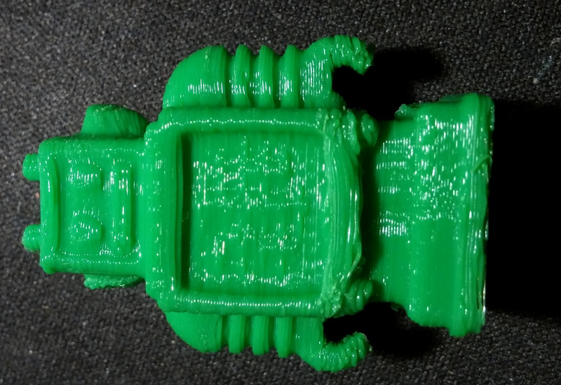
New print.. first layer seems much better now. This was done at 190°.
However, there's still some strangeness. The bottom part has a small gap between the walls that make up the sides. Also, halfway up, I get lots of thin threads hanging around (only along the short sides) and in one corner it looks like the filament was ripped out of the round part (best visible in the next picture). The top part (the one with the Pi logo) doesn't have that issue. Both parts were printed side-by-side at the same time. Also, the top layer has tiny gaps between the filament lines.
Here's where the real problem is.. on the top part, there's suddenly a gap between layers. Only on one side, and not on the bottom either, that one is nicely smooth and straight.
New print.. first layer seems much better now. This was done at 190°.

However, there's still some strangeness. The bottom part has a small gap between the walls that make up the sides. Also, halfway up, I get lots of thin threads hanging around (only along the short sides) and in one corner it looks like the filament was ripped out of the round part (best visible in the next picture). The top part (the one with the Pi logo) doesn't have that issue. Both parts were printed side-by-side at the same time. Also, the top layer has tiny gaps between the filament lines.

Here's where the real problem is.. on the top part, there's suddenly a gap between layers. Only on one side, and not on the bottom either, that one is nicely smooth and straight.
|
Re: Interpreting a test print October 31, 2014 05:51PM |
Admin Registered: 17 years ago Posts: 7,879 |
Is this with Skeinforge?
It looks like you might have a missing retract before a move, so it leaves strings and then a gap at the start of the next run. If the retract speed is too fast it can stall the extruder motor and have a similar effect.
If it is with Skeinforge the speed should be correct. You might need to increase the distance a little for a less viscous plastic. Try 1.5mm instead of 1mm.
[www.hydraraptor.blogspot.com]
|
Re: Interpreting a test print October 31, 2014 06:25PM |
Registered: 9 years ago Posts: 157 |
That was done with Craftware. I tried Skeinforge just now. Same STL.
A lot less issues.. but I'm running into trouble using skeinforge with anything that needs support. Last thing I printed with support was unusable due to the support being merged so firmly with the part, that it wouldn't come off without major destruction.
Edit: Nevermind, just found some info on supports, will give it a spin.
Are there any known issues using pypy? It speeds up the slicing a lot.
Edited 1 time(s). Last edit at 10/31/2014 06:58PM by Arakon.
|
Re: Interpreting a test print October 31, 2014 06:45PM |
Registered: 10 years ago Posts: 541 |
Quote
nophead
Sorry Neil, I don't understand what you are saying here. The bed should be levelled before Z_HOME_POS is calibrated. After that it is determined by the nozzle length, exact position of the top Z bracket, etc. It doesn't depend on where the X carriage was when you levelled the bed. The back two pillars should always be tight against the washers, only the front two are adjusted to get it level front to back.
What I was attempting to illustrate is that the initial setting of the Z-screws will determine how much adjustment is required on the front pillars to achieve a parallel bed. After installing the washers under the front pillars (temporarily) I measure the bed height at the front and use that to set the initial Z-screw height. This then results in a smaller adjustment of the front pillars to level the bed than if the Z-screw height was set randomly higher.
This has nothing to do with setting the Z_HOME_POS value. I hope this is a little clearer.
I try to write with consideration for all nationalities. Please let me know if something is unclear.
Printing with Mendel90 from fedora 25 using Cura, FreeCAD, MeshLab, OpenSCAD, Skeinforge and Slic3r tools.
|
Re: Interpreting a test print November 01, 2014 05:40AM |
Admin Registered: 17 years ago Posts: 7,879 |
I am still not following. I think you must be using a different levelling procedure from the one in the manual.
The back pillars are fixed, so the position of the front pillars to level the bed is predetermined by the geometry of the machine. Yes, the starting point should be one washer thickness gap. The first touch off point is the middle of the back, which does not depend on the front adjustment. The lead screws are adjusted to make the rear left and right corners the same as the mid point and then the front pillars are adjusted to make them the same.
In practice some iteration is needed but I don't see any dependency on the initial position of the Z screws.
[www.hydraraptor.blogspot.com]
|
Re: Interpreting a test print November 01, 2014 06:34AM |
Registered: 10 years ago Posts: 541 |
Quote
nophead
In practice some iteration is needed but I don't see any dependency on the initial position of the Z screws.
No dependency, the procedure eases levelling the bed i.e.
1) Place the temporary washers under the front pillars
2) Use the dial gauge to measure the front-left and front-right bed height
3) Manually adjust the Z-screws to match the measurements taken in step 2
4) Perform the bed-levelling procedure per the Manual
The idea is to get the bed near-planar before you start adjusting the pillars so you don't have the situation where the rear of the bed is significantly above, or below, the front at the start of levelling. By doing this, I get my bed levelled extremely accurately, quickly, and with minimal adjustment (from the one-washer thickness) of the front pillars.
Edited 1 time(s). Last edit at 11/01/2014 06:35AM by neildarlow.
I try to write with consideration for all nationalities. Please let me know if something is unclear.
Printing with Mendel90 from fedora 25 using Cura, FreeCAD, MeshLab, OpenSCAD, Skeinforge and Slic3r tools.
|
Re: Interpreting a test print November 01, 2014 06:49AM |
Registered: 9 years ago Posts: 157 |
Gnah.. I don't get it. I had adjusted the Z_Home_Pos to where it printed a 0.23 mm skirt all around when printing 0.2mm layers. Today I start a print, and the skirt is perfectly even.. except it's now 0.3mm thick and the first layer has visible lines. If something had shifted, i.e. one screw or one motor slipped, I wouldn't still get a perfectly even skirt.
|
Re: Interpreting a test print November 01, 2014 09:24AM |
Admin Registered: 17 years ago Posts: 7,879 |
Have you checked the gcode? If you are switching slicers they may be configured differently.
Sorry Neil, I still don't understand what you are saying. I don't know what you mean by "Manually adjust the Z-screws to match the measurements taken in step 2"?
[www.hydraraptor.blogspot.com]
Sorry Neil, I still don't understand what you are saying. I don't know what you mean by "Manually adjust the Z-screws to match the measurements taken in step 2"?
[www.hydraraptor.blogspot.com]
|
Re: Interpreting a test print November 01, 2014 09:32AM |
Registered: 9 years ago Posts: 157 |
|
Re: Interpreting a test print November 01, 2014 01:10PM |
Admin Registered: 17 years ago Posts: 7,879 |
Check the top and bottom bar clamps and the limit switch are not loose. I can't think of anything else that would cause it to vary.
Is the position of the Z screw pointers at the home position changing?
[www.hydraraptor.blogspot.com]
Is the position of the Z screw pointers at the home position changing?
[www.hydraraptor.blogspot.com]
|
Re: Interpreting a test print November 01, 2014 04:09PM |
Registered: 9 years ago Posts: 157 |
Thanks, but they're all firm and the pointers seem to stay in the same direction too. I wonder if something went out of whack because I turned the printer sideways and back again.. currently it seems to print fine again with the same settings.
I installed some LED strips, directly to the 12V line of the power supply. They flicker while printing.. does the Melzi board (or the motors for that matter) really interfere that strongly on the power line?
The 12V connector/power wires are slightly warm (37° according to my infrared thermometer), but not hot.
Edited 2 time(s). Last edit at 11/01/2014 04:11PM by Arakon.
|
Re: Interpreting a test print November 01, 2014 07:10PM |
Registered: 9 years ago Posts: 157 |
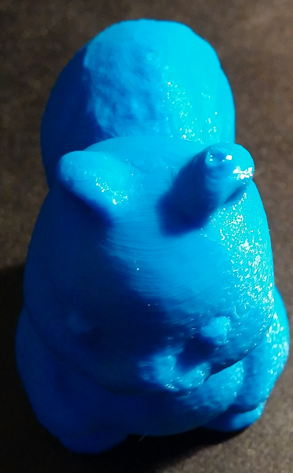
I'm quite happy with the print quality now. Only one issue seems to remain.. This was printed with 0.1mm layer height, nice and smooth, except it left a blob at the spot where the print finished. I am using your end code and skeinforge.I didn't notice this issue with prints that end in a flat surface, and less with bumpy surfaces, but I still usually get a fine "hair" pulled up by the extruder.
Edited 1 time(s). Last edit at 11/01/2014 07:12PM by Arakon.
Edited 1 time(s). Last edit at 11/01/2014 07:12PM by Arakon.
|
Re: Interpreting a test print November 02, 2014 07:14AM |
Admin Registered: 17 years ago Posts: 7,879 |
Yes the PSU voltage will change by a substantial faction of a volt when the bed heater switches on and off. The LED lights I used are constant current, so are not affected by voltage changes, but simple ones with resistors will be.
To remove the string at the end un-comment this line in end.gcode:
G1 X-100 Y100 F9000 ; go to back
That will move the nozzle away quickly horizontally before the slow upward movement. It might help with the ear but if that ear is higher than the other it will be tricky to print as it will slow right down because of the minimum layer time. One solution is to print two at a time or add a dummy pillar some distance away to allow the fan to traverse over the ear between each layer.
Edited 1 time(s). Last edit at 11/02/2014 09:04AM by nophead.
[www.hydraraptor.blogspot.com]
|
Re: Interpreting a test print November 02, 2014 07:17AM |
Registered: 9 years ago Posts: 157 |
Sorry, only registered users may post in this forum.