X-carriage in OpenScad
Posted by dc42
|
X-carriage in OpenScad May 29, 2014 05:48PM |
Registered: 10 years ago Posts: 14,672 |
In case anyone else wants to modify the X-carriage, I have recreated the design in OpenScad. You can find it at [github.com]. I've cleaned up the thin edge that didn't print very well in the original, extended the x-runner bearing slot a little, and left out the mounting for the original IR sensor. Apart from that, it's very much like the original.
It has an option for a slot for a force-sensitive resistor that can be enabled by changing a line near the top of the file. However, if you enable that option, then you will need to strengthen that material below the slot; because in the design as-is, the slots widen over time, leading to head sag.
Large delta printer [miscsolutions.wordpress.com], E3D tool changer, Robotdigg SCARA printer, Crane Quad and Ormerod
Disclosure: I design Duet electronics and work on RepRapFirmware, [duet3d.com].
|
Re: X-carriage in OpenScad May 30, 2014 05:19AM |
Registered: 10 years ago Posts: 378 |
Nice job! I did something similar in Sketchup just working on the STL file, because I totally lacked the dedication required to do it in OpenSCAD... However, I made the back part (the one that is a bit badly printed as default) a little bit too thick so it would stick against the Z aluminium extrusion and I had to file it down. Also made it just the right length to fit between the grooves on the linear bearing so I could use lock rings to secure it (since I have had it nearly slip off a couple times), but it turned out the bearing would then restrict X movement at the high end (right-hand side).
I see that while the sensor mount is no longer there, there are still some "vestigial structures" for it. I removed it all, but instead extended the whole front side a bit downwards to just get more surface area against the bearing. Is there any particular reason to keep part of the sensor mount bits?
Attaching mine for comparision. I do not recommend anyone actually print this, since it does not quite fit. dc42's is likely way better.
Edit: I would like to add something to just grip on the bearing better (maybe something as simple as a grub screw), but I'll certainly base it on this, because OpenSCAD.
Edited 1 time(s). Last edit at 05/30/2014 05:23AM by jstck.
|
Re: X-carriage in OpenScad May 30, 2014 06:52AM |
Registered: 10 years ago Posts: 14,672 |
John, I kept the "vestigial structures" simply so that it would grip the bearing as well as the original does. I dare say some of them could be removed. Which side do you mean by the "front side" - the one with the nozzle mounting screw holes in it?
I like the idea of a grub screw or similar to lock it on to the bearing - I've had the x-carriage come off.
Large delta printer [miscsolutions.wordpress.com], E3D tool changer, Robotdigg SCARA printer, Crane Quad and Ormerod
Disclosure: I design Duet electronics and work on RepRapFirmware, [duet3d.com].
|
Re: X-carriage in OpenScad May 30, 2014 07:28AM |
Registered: 10 years ago Posts: 1,230 |
Quote
dc42
..I like the idea of a grub screw or similar to lock it on to the bearing - I've had the x-carriage come off.
I don't like the idea of opening the grip of the printed by pressure from a grub screw, would be better to wrap it more tightly around the bearing
BTW, I printed that part solid in ABS and it shrunk to a very close fit
Erik
|
Re: X-carriage in OpenScad May 30, 2014 08:00AM |
Registered: 10 years ago Posts: 14,672 |
Quote
ormerod168
Quote
dc42
..I like the idea of a grub screw or similar to lock it on to the bearing - I've had the x-carriage come off.
I don't like the idea of opening the grip of the printed by pressure from a grub screw, would be better to wrap it more tightly around the bearing
BTW, I printed that part solid in ABS and it shrunk to a very close fit
Erik
I was considering using a piece of locking to secure the x-carriage to the bearing. Maybe I'll add holes for locking wire in the next version.
Large delta printer [miscsolutions.wordpress.com], E3D tool changer, Robotdigg SCARA printer, Crane Quad and Ormerod
Disclosure: I design Duet electronics and work on RepRapFirmware, [duet3d.com].
|
Re: X-carriage in OpenScad May 30, 2014 08:44AM |
Registered: 13 years ago Posts: 1,611 |
The grooves in the linear bearings are actually for circlips. We happen to have a competitors machine in-house, that uses an awful lot of them to locate the bearings!
Our current x-carriage, with a slightly longer bearing slot, is on github (I put it up there a couple of weeks ago, having been chastened by dc!). It also has a couple of little nodule that locate in the bearing grooves, which also helps retain the bearing. See: [github.com]
Ian
RepRapPro tech support
|
Re: X-carriage in OpenScad May 30, 2014 12:17PM |
Registered: 10 years ago Posts: 378 |
Quote
dc42
John, I kept the "vestigial structures" simply so that it would grip the bearing as well as the original does. I dare say some of them could be removed. Which side do you mean by the "front side" - the one with the nozzle mounting screw holes in it?
I like the idea of a grub screw or similar to lock it on to the bearing - I've had the x-carriage come off.
Yes, the side with the nut traps and that the hotend sits on. If you look at the STL file I uploaded earlier, you'll see it just extends a bit further down.
A grub screw wouldn't need that much "bite" to keep it in place (just has to overcome the friction between bearing and rod), a small hole is lined up with the circlip groove in the bearing should keep it tight. Too much, and it could force the x-carriage open a bit which would make it not fit as tight. An option (as I think you mentioned with "lockwire") would be a groove on the inside of the x-carriage that lines up with the one in the bearing, and just pushing some wire through there.
While it would be nice if it would just "grab on" by itself, it is difficult to make it last. I've had it sit pretty tight at first and then come loose (after a while of printing), even with ABS. Heat, motion, and maybe some lubricant from the bearing getting in there.
Those little nubs on the droftarts/reprappro one might work nicely to hold it in place though, and might just be the simplest possible solution.
|
Re: X-carriage in OpenScad May 30, 2014 01:34PM |
Registered: 10 years ago Posts: 859 |
While onboard ship, and without any circlips or grub screws to hand. I ended up using Super Glue as a semi permanent fix. It's worked supprisingly well. I'm not a lover of the Grub Screw location, as you really need to get it at the point of just touching inside the groove, else to tight is going to open up the print around the bearing, and to slack, and the bearings still going to rattle back and forth. While Super Glue does adhere to PLA, it can still be peeled off if need be, and in this case it got me out of a hole, and allowed me to keep printing. Circlips are by far the best way to hold this bearing inside the Carrage I think.
Kim..
Please send me a PM if you have suggestions, or problems with Big Blue 360.
I won't see comments in threads, as I move around to much.
Working Link to Big Blue 360 Complete
Kim..
Please send me a PM if you have suggestions, or problems with Big Blue 360.
I won't see comments in threads, as I move around to much.
Working Link to Big Blue 360 Complete
|
Re: X-carriage in OpenScad May 30, 2014 03:12PM |
Registered: 10 years ago Posts: 1,230 |
Quote
KimBrown
... I'm not a lover of the Grub Screw location, as you really need to get it at the point of just touching inside the groove, else to tight is going to open up the print around the bearing, and to slack, and the bearings still going to rattle back and forth..
my point exactly! - I did this instead, ABS solid print:
..and notice the heavy industrial grease coming out the bearing, no it don't help, yes it still rattles on the rod
Erik
|
Re: X-carriage in OpenScad June 02, 2014 06:48PM |
Registered: 10 years ago Posts: 378 |
I butchered your design, and after trying to comment what bit does what, I made some potential improvements:
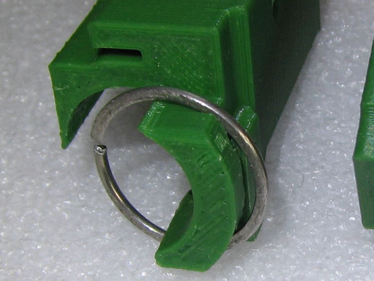
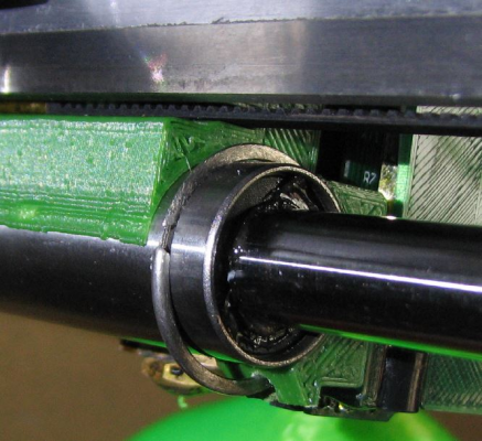
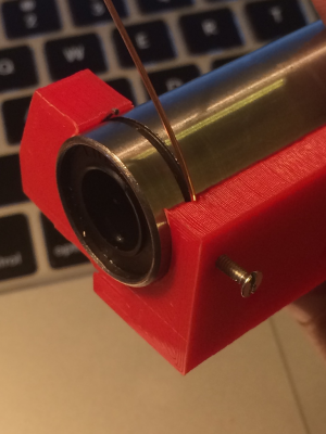
I mostly wanted to make sure the carriage cannot come off the bearing (after having that happen twice, and almost several times more). Even if the carriage fits snugly when new, it seems to become loose over time. With this, it can easily be locked in place in one of two different ways; either with a piece of wire/cable pushed through the groove, or with a setscrew. Pictures are of it mounted on a spare bearing, it's not yet on the printer. Printed it in ABS, but PLA should work just as well, especially if you are mostly printing PLA (the earlier one I did based on the original mount was PLA and was doing seemlingly fine). The size of the groove and the setscrew hole diameter are easily configurable in the .scad file, you probably want a larger hole if you have one of those little allen-head grubscrews.
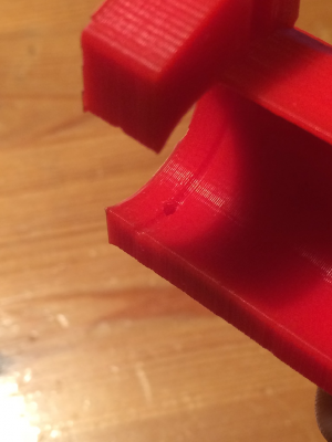
The groove on the inside of the X carriage, as well as the setscrew hole:
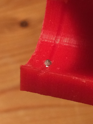
Tip of setscrew. This is a plain M2 screw that I made a bit pointy. It doesn't have to be screwed in at all tight, just so it touches the bearing is enough. That won't push on the bearing, but it will keep it from coming loose with any reasonable amount of force. The bearing can still rotate, and can move a fraction of a millimeter sideways, which is fine.
A piece of thin cable pushed through the hole. This absolutely locked it in place, but was a bit tricky to install (had to turn the bearing and push the cable at the same time), and would be very difficult to do on the printer. Also after trimming the cable, it was very difficult to remove it...
A piece of 0.8mm MIG welding wire. This was a lot easier to install. Here too, the bearing can move a tiny bit, but it absolutely cannot come off. I could not push it off with my fingers. Setscrew is not tightened (it would just push on the wire).
Edit: I apparently made it too tall (wide) and was too tired last night to check. Have updated the .scad/.stl files with ones that are of more reasonable length.
Edited 2 time(s). Last edit at 06/03/2014 03:04AM by jstck.
- Removed the bits for the old sensor mount.
- Added a groove to match the one in the bearing, for inserting a piece of wire to lock it in place.
- Made a hole for a setscrew.
- Adjusted the total length so the other bearing groove (on the "low X" side) will line up with the edge of the carriage, if someone wants a circlip or something there for some reason.
- Made the number of teeth configurable for no particular reason. Up to 13 will fit.
I mostly wanted to make sure the carriage cannot come off the bearing (after having that happen twice, and almost several times more). Even if the carriage fits snugly when new, it seems to become loose over time. With this, it can easily be locked in place in one of two different ways; either with a piece of wire/cable pushed through the groove, or with a setscrew. Pictures are of it mounted on a spare bearing, it's not yet on the printer. Printed it in ABS, but PLA should work just as well, especially if you are mostly printing PLA (the earlier one I did based on the original mount was PLA and was doing seemlingly fine). The size of the groove and the setscrew hole diameter are easily configurable in the .scad file, you probably want a larger hole if you have one of those little allen-head grubscrews.
The groove on the inside of the X carriage, as well as the setscrew hole:
Tip of setscrew. This is a plain M2 screw that I made a bit pointy. It doesn't have to be screwed in at all tight, just so it touches the bearing is enough. That won't push on the bearing, but it will keep it from coming loose with any reasonable amount of force. The bearing can still rotate, and can move a fraction of a millimeter sideways, which is fine.
A piece of thin cable pushed through the hole. This absolutely locked it in place, but was a bit tricky to install (had to turn the bearing and push the cable at the same time), and would be very difficult to do on the printer. Also after trimming the cable, it was very difficult to remove it...
A piece of 0.8mm MIG welding wire. This was a lot easier to install. Here too, the bearing can move a tiny bit, but it absolutely cannot come off. I could not push it off with my fingers. Setscrew is not tightened (it would just push on the wire).
Edit: I apparently made it too tall (wide) and was too tired last night to check. Have updated the .scad/.stl files with ones that are of more reasonable length.
Edited 2 time(s). Last edit at 06/03/2014 03:04AM by jstck.
|
Re: X-carriage in OpenScad June 03, 2014 03:20AM |
Registered: 10 years ago Posts: 176 |
Has there been an upgraded X-idler tensioner for the belt that I missed? I find that a) the belt is very difficult to insert nicely, and b) the tensioning was difficult - not much movement on the motor it difficult to keep tension up while tightening the screws.
I would have thought that the end of the cross arm could just have a tensioning screw like the way you tension the Prusa i3.
I would have thought that the end of the cross arm could just have a tensioning screw like the way you tension the Prusa i3.
|
Re: X-carriage in OpenScad June 03, 2014 03:26AM |
Registered: 10 years ago Posts: 157 |
I have also tensioned the X belt by shifting the part that holds the idler,
and by that I mean the green part that is on the bottom of this image:
[reprappro.com]
RS-Online Ormerod #263, Kossel mini with Minitronics, Prusa i3 MK2
and by that I mean the green part that is on the bottom of this image:
[reprappro.com]
RS-Online Ormerod #263, Kossel mini with Minitronics, Prusa i3 MK2
|
Re: X-carriage in OpenScad June 03, 2014 06:28AM |
Registered: 10 years ago Posts: 378 |
|
Re: X-carriage in OpenScad June 03, 2014 07:08AM |
Registered: 10 years ago Posts: 14,672 |
I too found it hard to tension the x-belt using the motor screws, until I discovered a trick. Loosen the motor screw at the far end of the x-plate a little, and the other one a lot. Then push the motor to tension the belt as much as you can. This will cause the motor to tilt a little because of the force of the x-belt on the pulley. Tighten the motor screw at the far end first, then the other one - which removes the tilt and tightens the belt.
Large delta printer [miscsolutions.wordpress.com], E3D tool changer, Robotdigg SCARA printer, Crane Quad and Ormerod
Disclosure: I design Duet electronics and work on RepRapFirmware, [duet3d.com].
Large delta printer [miscsolutions.wordpress.com], E3D tool changer, Robotdigg SCARA printer, Crane Quad and Ormerod
Disclosure: I design Duet electronics and work on RepRapFirmware, [duet3d.com].
|
Re: X-carriage in OpenScad June 03, 2014 04:18PM |
Registered: 10 years ago Posts: 1,230 |
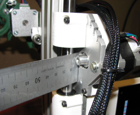
I use a steel ruler and the leverage of the smooth rod on the pulley to tighten the belt
Erik
Erik
|
Re: X-carriage in OpenScad June 06, 2014 03:08AM |
Registered: 10 years ago Posts: 378 |
Not sure if it's just in my case or a more general thing, but I think the bearing on the back of this X carriage sits just a little bit higher than the default one. If the extruder is properly seated in it's "notch", the bearing can catch on the motor. On the way "in", it just moved the motor out of the way, but on the way "out", it got stuck and the X motor was grinding and skipping. I have my extruder on the innermost notch so this happened during homing (X homed fine, but it caught on its way to home Z). If you are using this carriage, do check that you have some clearance between the X carriage bearing and the extruder assembly.
I'm printing a hinged extruder anyway, and I'll just modify the mount on that so it sits a little bit higher up. Just a couple millimeters does it.
I'm printing a hinged extruder anyway, and I'll just modify the mount on that so it sits a little bit higher up. Just a couple millimeters does it.
|
Re: X-carriage in OpenScad June 06, 2014 03:49AM |
Registered: 10 years ago Posts: 14,672 |
Quote
jstck
Not sure if it's just in my case or a more general thing, but I think the bearing on the back of this X carriage sits just a little bit higher than the default one. If the extruder is properly seated in it's "notch", the bearing can catch on the motor..
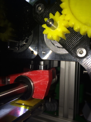
Strange, I don't have that problem, even though I have a nut between the x-carriage and the bearing:
Large delta printer [miscsolutions.wordpress.com], E3D tool changer, Robotdigg SCARA printer, Crane Quad and Ormerod
Disclosure: I design Duet electronics and work on RepRapFirmware, [duet3d.com].
|
Re: X-carriage in OpenScad June 06, 2014 05:15AM |
Registered: 10 years ago Posts: 378 |
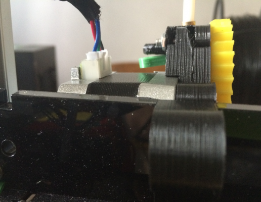
I fiddled a bit more with it, and I can reproduce it only if the extruder hangs a bit crooked (so the inside corner of the motor hangs down a bit). It pretty easily gets that way though (my stock extruder has even curved itself from heat/weight or something). Even so, I have less than 2mm clearance.
This is how much clearance I have with the extruder snugly in place (crappy picture, I know, darn daylight in background forcing me to use flash):
This is how crooked the extruder has to sit for the inside corner of the motor to touch the screw on the back of the X carriage. Not a whole lot. Easily gets this way just from the hotend pulling slightly on the bowden tube, or the extruder pulling on the filament from the reel.
It got a bit better when I tightened the screw a bit, so the nozzle assembly points just a tiny bit upwards (which doesn't matter much given the way your sensor is mounted), so it should be a bit safer now. Could also just add some electrical tape in the notch on the acrylic X rib to both raise the extruder up a bit and to make it sit tighter.
I can't say for certain that it is due to this X carriage (comparing with the stock one they sure look similar), it's just that this happened a couple times after I changed the X carriage, and never happened before (with the same extruder bracket). Probably just because the bolt with the bearing sits a bit "tighter" and ends up in a slightly different position. It's not a serious problem in any case and pretty easily fixed once you know about it, but it might be worth looking out for. It is a bit odd though how different it looks on your printer compared to mine, if I added a nut in between I would have very little clearance.
Edit: I see you have a countersunk screw instead of a cap-head one, that would certainly get me another millimeter or two. Just double checked, and I at least didn't misread the assembly instructions. Could just replace it if I find an appropriate one. Also looks like you have the aluminium X rib, might it be that it is a millimeter or two taller?
Edited 2 time(s). Last edit at 06/06/2014 05:20AM by jstck.
This is how much clearance I have with the extruder snugly in place (crappy picture, I know, darn daylight in background forcing me to use flash):
This is how crooked the extruder has to sit for the inside corner of the motor to touch the screw on the back of the X carriage. Not a whole lot. Easily gets this way just from the hotend pulling slightly on the bowden tube, or the extruder pulling on the filament from the reel.
It got a bit better when I tightened the screw a bit, so the nozzle assembly points just a tiny bit upwards (which doesn't matter much given the way your sensor is mounted), so it should be a bit safer now. Could also just add some electrical tape in the notch on the acrylic X rib to both raise the extruder up a bit and to make it sit tighter.
I can't say for certain that it is due to this X carriage (comparing with the stock one they sure look similar), it's just that this happened a couple times after I changed the X carriage, and never happened before (with the same extruder bracket). Probably just because the bolt with the bearing sits a bit "tighter" and ends up in a slightly different position. It's not a serious problem in any case and pretty easily fixed once you know about it, but it might be worth looking out for. It is a bit odd though how different it looks on your printer compared to mine, if I added a nut in between I would have very little clearance.
Edit: I see you have a countersunk screw instead of a cap-head one, that would certainly get me another millimeter or two. Just double checked, and I at least didn't misread the assembly instructions.
 Could just replace it if I find an appropriate one. Also looks like you have the aluminium X rib, might it be that it is a millimeter or two taller?
Edited 2 time(s). Last edit at 06/06/2014 05:20AM by jstck.
|
Re: X-carriage in OpenScad June 06, 2014 06:03AM |
Registered: 10 years ago Posts: 14,672 |
Yes, I fitted a countersunk screw to give room to add the nut under the bearing. However, I'm wondering whether the top of your x-carriage may not have been level in the y-direction, and your print head sagging. This is a common problem. I had to use a 10mm bearing instead of the 9mm one supplied. Also, the aluminium x-plate helps because it is 5mm thick, whereas the acrylic was only 4.55mm at one end and 4.65mm at the other end.
EDIT: I've just taken some measurements, and the bearing mounting surface is 3.80mm above the top of the linear bearing hole in the x-carriage I received from RRP, 3.95mm in one I printed from RRP's file, and 3.90mm in one I printed from my file. So if there is a difference, it's small.
Edited 4 time(s). Last edit at 06/06/2014 06:18AM by dc42.
Large delta printer [miscsolutions.wordpress.com], E3D tool changer, Robotdigg SCARA printer, Crane Quad and Ormerod
Disclosure: I design Duet electronics and work on RepRapFirmware, [duet3d.com].
|
Re: X-carriage in OpenScad June 06, 2014 05:12PM |
Registered: 10 years ago Posts: 378 |
My X carriage and hotend was maybe a little bit "below" level, but tightening it up to level or even above doesn't make much difference in the clearance (fractions of a millimeter). Anyway, some electrical tape in the notch on the X rib makes the extruder stay in place much better, might be this will be the last I see of it.
Sorry, only registered users may post in this forum.
