New Ormerod 2 feedback
Posted by MikeyD
|
New Ormerod 2 feedback October 17, 2014 06:49PM |
Registered: 9 years ago Posts: 32 |
I thought I would write down my recent experience assembling and commissioning our Ormerod 2 before I forget. We took delivery on Wednesday morning, it is now Friday night. I did have other things on but I estimate I have spent 15 hours so far to get where I am. Sorry for the long ramble but the RepRapPro instructions did say any feedback would be welcome.
Assembly: The instructions on the reprappro website can't be faulted. Very well explained using both text and pictures. I didn't find anything I could call an error. The only part lacking is the best way to guide the filament from the spool to the extruder motor. So far I have been guiding it over a couple of metal rods clamped to a lab stand but I will improve that with something connected to the Ormerod frame.
Wiring: There were 2 problems with the supplied wiring looms, which were easily spotted because they didn't match the instructions. First one was the control board end of the Y stop loom only has a 2 pin header (SIL plug) which needed changed for a 3 pin, leaving the middle pin unconnected. Easy for me as we happened to have a bare 3 pin header and new crimps in stock. Second problem was the proximity sensor wiring again at the board end needed the red and blue swapped as the header only goes on one way round.
Commissioning: Connecting via USB was no problem but I lost an hour or two getting the web interface to work. I think there must be an Arduino issue when I put it on our site network. It understood the IP address and netmask because I could ping it remotely but firefox wasn't having any of it and chrome would sort of try to slowly render the page then give up. The computer I had it connected to with USB had 2 gig-e ports so I put the arduino back to it's default 192.168.1.14 address and configured the spare computer ethernet port to a static 192.168.1.. address and linked them direct. Result, chrome works fine, but obviously only from the local PC. I will try to go back and look into this with wireshark at some point, but it isn't a show-stopper.
Calibration: 3d printing is/was new to me and there is a learning curve. GCodes are becoming quite familiar to me now though. I had no problem with any of the 3 axis homing etc. It was only the extruder drive which gave me bother. Basically no amount of cog 'fettling' or aligning would let me feed without the occasional motor stutter. I have for now changed the maximum current up to 1100 mA which works fine, although I am aware the motor is running at about 45C going by an IR thermometer.
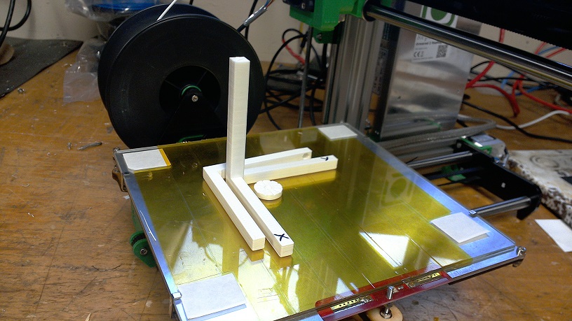
Printing: Instructions say to set the Z axis zero so you can just see daylight. Not that easy really. First print attempt looked ok to begin with but the nozzle was to high so on the second pass the nozzle and the proximity sensor swept it out the way. Second attempt much closer to the deck started ok, but again prox caught it. Removed prox sensor and re-fitted after a bit of fettling a mm or so higher. Third attempt also started good but just didn't seem to be sticking. Removed all the tape and tried on plain glass after cleaning with IPA. Worse if anything. Reapplied tape and checked bed temperature with IR gun and it looked low. Set bed temp to 65C and got a result.. Until I paused it an hour into the print for lunch and came back to find the PC automatically installing updates, and had lost connection. Not the Ormerod's fault though. Restarted at 14:00 and all went well, finished the ORMAXIS print at 16:30. I have attached a photo of the result.
In short I'm very happy with the exprience so far.
Once again, sorry for the long post, but I hope it might help someone.
Assembly: The instructions on the reprappro website can't be faulted. Very well explained using both text and pictures. I didn't find anything I could call an error. The only part lacking is the best way to guide the filament from the spool to the extruder motor. So far I have been guiding it over a couple of metal rods clamped to a lab stand but I will improve that with something connected to the Ormerod frame.
Wiring: There were 2 problems with the supplied wiring looms, which were easily spotted because they didn't match the instructions. First one was the control board end of the Y stop loom only has a 2 pin header (SIL plug) which needed changed for a 3 pin, leaving the middle pin unconnected. Easy for me as we happened to have a bare 3 pin header and new crimps in stock. Second problem was the proximity sensor wiring again at the board end needed the red and blue swapped as the header only goes on one way round.
Commissioning: Connecting via USB was no problem but I lost an hour or two getting the web interface to work. I think there must be an Arduino issue when I put it on our site network. It understood the IP address and netmask because I could ping it remotely but firefox wasn't having any of it and chrome would sort of try to slowly render the page then give up. The computer I had it connected to with USB had 2 gig-e ports so I put the arduino back to it's default 192.168.1.14 address and configured the spare computer ethernet port to a static 192.168.1.. address and linked them direct. Result, chrome works fine, but obviously only from the local PC. I will try to go back and look into this with wireshark at some point, but it isn't a show-stopper.
Calibration: 3d printing is/was new to me and there is a learning curve. GCodes are becoming quite familiar to me now though. I had no problem with any of the 3 axis homing etc. It was only the extruder drive which gave me bother. Basically no amount of cog 'fettling' or aligning would let me feed without the occasional motor stutter. I have for now changed the maximum current up to 1100 mA which works fine, although I am aware the motor is running at about 45C going by an IR thermometer.
Printing: Instructions say to set the Z axis zero so you can just see daylight. Not that easy really. First print attempt looked ok to begin with but the nozzle was to high so on the second pass the nozzle and the proximity sensor swept it out the way. Second attempt much closer to the deck started ok, but again prox caught it. Removed prox sensor and re-fitted after a bit of fettling a mm or so higher. Third attempt also started good but just didn't seem to be sticking. Removed all the tape and tried on plain glass after cleaning with IPA. Worse if anything. Reapplied tape and checked bed temperature with IR gun and it looked low. Set bed temp to 65C and got a result.. Until I paused it an hour into the print for lunch and came back to find the PC automatically installing updates, and had lost connection. Not the Ormerod's fault though. Restarted at 14:00 and all went well, finished the ORMAXIS print at 16:30. I have attached a photo of the result.
In short I'm very happy with the exprience so far.
Once again, sorry for the long post, but I hope it might help someone.
|
Re: New Ormerod 2 feedback October 18, 2014 09:16AM |
Registered: 10 years ago Posts: 1,230 |
Quote
MikeyD
..Printing: Instructions say to set the Z axis zero so you can just see daylight. Not that easy really...
Thank You for posting! - I think a better definition would be "so you just cannot see daylight" - if not, then first layer (e.g. 0,24) will be 0,24 + daylight
Do the hotend still include acoustic feedback aka the vibrating fan? - if so you can hear when the nozzle is touching the bed :-)
Erik
|
Re: New Ormerod 2 feedback October 18, 2014 10:07AM |
Registered: 9 years ago Posts: 146 |
|
Re: New Ormerod 2 feedback October 20, 2014 02:44AM |
Registered: 9 years ago Posts: 92 |
Hi there
Thanks for your post, nice to see someone else's first experience with the printer.
Also completed mine over the weekend. My results nowhere as good as yours but we definitely had some similar issues.
Also pushed the bed temp up a bit to get the print to stick.
Had the same issue with red and blue wires reversed on proximity sensor, and then had poor contact after I removed and reinserted the crimp into the housing. But so far still working. May consider replacing the houseing entirely for sake of good connections.
I definitely need to do some belt tightening though! Y-axis in particular.
At some point in the Z-axis part of the test print the nozzle tip seemed to be swimming in molten PLA. Brought the temp down from 185 to 182 and it seemed to improve. Thought the small surface area of that part of the print was not giving the PLA time to harden a little before the next pass, if that makes sense?
Only other problem was extruder temp varying during print. First third of print the temperature was rock steady, then suddenly started varying (up to 20 degrees), then it steadied for a while again, and then again started varying. I will check the thermistor wire for good connection before printing again. Other alternative is that the thermistor is failing. Any thoughts on this?
James
Edited 1 time(s). Last edit at 10/20/2014 02:45AM by jamesf.
|
Re: New Ormerod 2 feedback October 20, 2014 05:44AM |
Registered: 13 years ago Posts: 1,611 |
Hi MikeyD and James
Many thanks for your feedback, I'm really glad your experience has been relatively smooth! I don't think there's much I can add at the moment to other's comments. It sounds like you both had quite early kits; we had a few that went out with the Y endstop with a 2-way rather than 3-way housing (which we're happy to replace) before we spotted the mistake, and also a few looms that had the blue/red the wrong way around (this is relatively easy to fix, as you worked out). Sorry about that!
Our dirty secret... To guide the filament, we tape the end of the 3mm PTFE tube to the top of the Z axis, on the face of the z-upper-mount that faces down the x axis, with the other end in the extruder drive. On the Ormerod 1, there were slots in the x-axis-plate for the filament, but with the PSU in the way we can't use these. We've redesigned the z-upper-mount with a trap for the end of the tube, but haven't released it yet, as we're just preparing a couple of other tiny updates to the stl files.
James: The compensation piece is quite a tough first print, particularly the tall, thin part. It really tests the temperature control. If you're getting variation in temperature, and the extruded plastic is looking very liquid, the hot end may be running a little hot. Make sure the thermistor is located in the heater block correctly, and the wiring is solidly connected at every connector; the 3x2 hot end connector can get pulled around quite a lot, so poor crimping and/or connections there may give a variable reading.
Let me know if there's any other help you need, or feedback.
Ian
RepRapPro tech support
(I also write the instructions, so good to hear they were helpful for you!)
|
Re: New Ormerod 2 feedback October 20, 2014 09:59AM |
Registered: 9 years ago Posts: 32 |
ormerod168 and Amsterdamman: Thank you for confirming what I was thinking. I am now using the 'go down in 0.1mm steps until it plays a different tune, then back up 0.1mm' method of Z axis zero setting.
James: It does sound like a bad connection to me. If you haven't already the park the machine up and set the hot end to 180 degrees and start nudging/wiggling wires and connections to see if you can pin-point where the problem is.
Ian: I never thought of using PTFE tube to guide the filament from the spool to the extruder. We have lots of space so I was thinking of ignoring the spool mount altogether and move the reel to it's own stand to the right of the printer so it has a straight run to the extruder drive.
Today I have printed a part which we bought the machine for. It didn't come out perfect as we were a bit ambitious in DesignSpark how thin we could get some walls. I have since then printed out iamburny's pairs of extruder drive cogs and Z axis cogs from Thingiverse which look like useful upgrades and am now printing spare parts.
|
Re: New Ormerod 2 feedback October 21, 2014 07:36AM |
Registered: 10 years ago Posts: 2,472 |
Quote
MikeyD
Today I have printed a part which we bought the machine for. It didn't come out perfect as we were a bit ambitious in DesignSpark how thin we could get some walls. I have since then printed out iamburny's pairs of extruder drive cogs and Z axis cogs from Thingiverse which look like useful upgrades and am now printing spare parts.
Always make vertical walls that are thinner than (number of perimeters+0.5) an exact multiple of 0.5mm. e.g. if you have set the number of perimeters to 2 in Slic3r, then walls should be an exact multiple of 0.5mm unless they are thicker than 2.5mm. That's assuming you are using the standard perimeter width of 0.5mm in Slic3r (you can change that in advanced settings if you really need a different thickness of wall, in which case make the walls an exact multiple of whatever you have set the perimeter width). If the wall slopes (has draft), then the rule applies to the horizontal thickness of the cross-section rather than the wall thickness. I rarely go thinner than 2mm for most walls, and usually use 3mm for anything structural. The exception is prints that are prototypes for parts destined for injection moulding, where I often go down to 1.5mm and sometimes 0.5mm - but it will be used only for proof of design. Be careful on rounded corners that the wall thickness is the same all the way around (inner and outer radii are concentric and differ by exactly the wall thickness), otherwise you may find the corners print hollow. Be aware that layer bonds are relatively weak, so the part will have a greater strength in the XY plane than in the Z planes. Due to that fact, it is sometimes better to split the design into several parts that you glue, weld or bolt together so as to print the sections in an orientation that provides strength in the required plane. Plumber's solvent cement or acetone creates a chemical weld on ABS that is just as strong as the plastic, I expect there is a glue suitable for PLA.
Dave
|
Re: New Ormerod 2 feedback October 21, 2014 09:54AM |
Registered: 9 years ago Posts: 32 |
|
Re: New Ormerod 2 feedback October 23, 2014 09:37AM |
Registered: 9 years ago Posts: 73 |
Hi All
I've recently finished building my Ormerod 2 and as previously mentioned it was all pretty straight forward and very well explained in the instructions
I have had numerous problems with 90% of the wiring looms though. The connectors to the board were all loose and had a habit of coming off at inopportune moments.
I started off by replacing the connectors but found that while the crimped ends fitted the pins tightly outside the plastic connector as soon as they were inserted into a new connector they became loose again.
I ended up cutting off all connectors and replacing with simple crimped ends with a heatshrink covering. Does mean that all the wires have to be connected individually but it seems to have solved the problem and I haven't had any issues with loose wiring since.
The only other things that I've found were that it was nearly impossible to get the x axis carriage tight resulting in the nozzle bouncing. Temporary fix was to drill a hole in the bearing bracket to allow me to put a screw in so that I could tighten the bearing against the x spar. Have since modified the bracket with a captive nut and screw to serve the same purpose although it seems pretty much redundant as the new carrier I printed fitted much better straight away so think it was just a small fault with the original printed part.
Finally had a small issue with the probe hitting the prints. Giving the nozzle mount a 2mm offset on the fixing holes has cured this and doesn't appear to have detrimentally affected the probe readings.
Looking back at this it looks like I'm having a moan, I'm really not. I've enjoyed playing with it and am now getting some decent prints out that I'm pretty impressed with.
Playing with trying to get it to print faster now, with mixed results, but it's a pretty interesting process.
Jon
|
Re: New Ormerod 2 feedback October 28, 2014 06:17AM |
Registered: 9 years ago Posts: 82 |
Hi,
This seems to be the place to report some feedback, so here is mine, after having assembled my ormerod2 last week-end.
First I must say that I'm pretty new to 3D printing. It's my very first printer (bought from RS) so I'm not experienced at all with all the mecanical part of it.
And as the others, I will especially report problems I had (and still have), which of course should not hide all the steps that went perfectly fine and the magic happening when the first printed part takes shape. Also, some of the problems mentioned are my bad, for not following instructions to the letter.
I found the instruction rather complete, especially coupled with the picture. Being a non native english speaker I can speak a rather fluent english but I miss the mecanical vocabulary needed to understand everything explained in the documentation. So pictures are of great help.
I had some cold sweats cutting/fitting the belts: I actually had so few margin for Y axis belt that there was no overlap at all on the jaw. Luckily the tension and grip is sufficient (eard the nice E note, even compared it with my bass guitar ). Appart from that I had another cold sweat when checking continuity between heat bed cable and earth (I posted that on another subject).
Wiring : as for MickeyD "the control board end of the Y stop loom only has a 2 pin header (SIL plug) which needed changed for a 3 pin, leaving the middle pin unconnected." I had some spare connectors, but leaving the original crimped contacts made the connector loose on the new connector box. I might have to change them later.
The aluminum ring on the wires (to connect them to earth on the Duet box) leave sometimes to little length to be comfortably connected. This is especially true for the the proximity sensor wire (longuest, blue and red), which is not long enough for the shielded part to be in contact with the box once connected.
I was surprised to see the PSU/Duet fan not moving although it was directly connected to the +12V on the PSU. It might have been damaged during travel because one of the plastic legs (rotor/stator link) were broken and the fan structure was weakened, the pressure of the printed base for it was to much for it to spin correctly. While making tests to see if could have it spining if I released the pressure I broke it completely so I'll have to find another one...
Finally I had problems with the X axis movement. The motor sometimes ran smoothly, sometimes coud not make the carriage move as expected. Turns out the belt was over-tensioned. I'm still having issues for X>180 or so because I made a mistake when mounting the belt: I did not twist it on the correct side so the twist ended up between the cariage and the bearing. I have to correct that but as the printer is fully assembled now I lack courage to disassemble everything ...
...
Crasy how every little detail counts in the documentation...
During the first print (after homing the 3 axis) the Y carriage unplugged the contact switch. I tried to tighten it with a pair of pliers, but broke the crimp. So I ended up soldering both cables on the Y contact switch.
Finally I managed to print the first model to calibrate the printer axis. When I wanted to mount the measurement print I couldn't find the 35mm hex head M3 screw and spring... Is it supposed to be in the package?
Now the last problem I have, but it should probably go to a specific thread, is that while it worked ok for the first print, now the homing of the axis seems faulty. The Y contact still works, the LED on the duet board is working ok. But when homing the Y axis the plate just moves 5mm and stops, considering itself homed wherever it was standing. The Z axis just goes up until I switch off the printer. Only the X axis homes OK. And motors are able to move in both directions if I send the orders manually, so it doesn't look like a mecanical problem (thinking about it it seems that motors are reacting the opposite way they should, the Y motor thinking it's in position, as if the switch has reversed the ON/OFF logic, and the Z motor going up instead of down to reach the proper IR threshold). I will re-check every wiring, maybe try to rework the cable shielding, and get back to "factory defaults" to see how it goes.
Anyway I have to say that as complicated and long as it was to build this up I admired the intelligent design of the parts/printer and there's something magical to see the first part taking shape under your eyes.
This seems to be the place to report some feedback, so here is mine, after having assembled my ormerod2 last week-end.
First I must say that I'm pretty new to 3D printing. It's my very first printer (bought from RS) so I'm not experienced at all with all the mecanical part of it.
And as the others, I will especially report problems I had (and still have), which of course should not hide all the steps that went perfectly fine and the magic happening when the first printed part takes shape. Also, some of the problems mentioned are my bad, for not following instructions to the letter.
I found the instruction rather complete, especially coupled with the picture. Being a non native english speaker I can speak a rather fluent english but I miss the mecanical vocabulary needed to understand everything explained in the documentation. So pictures are of great help.
I had some cold sweats cutting/fitting the belts: I actually had so few margin for Y axis belt that there was no overlap at all on the jaw. Luckily the tension and grip is sufficient (eard the nice E note, even compared it with my bass guitar
). Appart from that I had another cold sweat when checking continuity between heat bed cable and earth (I posted that on another subject).Wiring : as for MickeyD "the control board end of the Y stop loom only has a 2 pin header (SIL plug) which needed changed for a 3 pin, leaving the middle pin unconnected." I had some spare connectors, but leaving the original crimped contacts made the connector loose on the new connector box. I might have to change them later.
The aluminum ring on the wires (to connect them to earth on the Duet box) leave sometimes to little length to be comfortably connected. This is especially true for the the proximity sensor wire (longuest, blue and red), which is not long enough for the shielded part to be in contact with the box once connected.
I was surprised to see the PSU/Duet fan not moving although it was directly connected to the +12V on the PSU. It might have been damaged during travel because one of the plastic legs (rotor/stator link) were broken and the fan structure was weakened, the pressure of the printed base for it was to much for it to spin correctly. While making tests to see if could have it spining if I released the pressure I broke it completely so I'll have to find another one...
Finally I had problems with the X axis movement. The motor sometimes ran smoothly, sometimes coud not make the carriage move as expected. Turns out the belt was over-tensioned. I'm still having issues for X>180 or so because I made a mistake when mounting the belt: I did not twist it on the correct side so the twist ended up between the cariage and the bearing. I have to correct that but as the printer is fully assembled now I lack courage to disassemble everything
...Crasy how every little detail counts in the documentation...
During the first print (after homing the 3 axis) the Y carriage unplugged the contact switch. I tried to tighten it with a pair of pliers, but broke the crimp. So I ended up soldering both cables on the Y contact switch.
Finally I managed to print the first model to calibrate the printer axis. When I wanted to mount the measurement print I couldn't find the 35mm hex head M3 screw and spring... Is it supposed to be in the package?
Now the last problem I have, but it should probably go to a specific thread, is that while it worked ok for the first print, now the homing of the axis seems faulty. The Y contact still works, the LED on the duet board is working ok. But when homing the Y axis the plate just moves 5mm and stops, considering itself homed wherever it was standing. The Z axis just goes up until I switch off the printer. Only the X axis homes OK. And motors are able to move in both directions if I send the orders manually, so it doesn't look like a mecanical problem (thinking about it it seems that motors are reacting the opposite way they should, the Y motor thinking it's in position, as if the switch has reversed the ON/OFF logic, and the Z motor going up instead of down to reach the proper IR threshold). I will re-check every wiring, maybe try to rework the cable shielding, and get back to "factory defaults" to see how it goes.
Anyway I have to say that as complicated and long as it was to build this up I admired the intelligent design of the parts/printer and there's something magical to see the first part taking shape under your eyes.
|
Re: New Ormerod 2 feedback October 28, 2014 06:42AM |
Registered: 13 years ago Posts: 1,611 |
Hi mat_fr
Glad to hear you are just about there, it sounds like you have overcome most difficulties. You really do need to change the twisted part of the belt on the X axis, though!
For you other problems:
The M3x35 screw and spring for the axis compensation wheel are not supplied; I keep meaning to update those instructions! You really don't need a special bolt; use any screw you have available. There should be a spare screw of each size in the kit. One of the crosshead screws that came out of the motor should be long enough, is threaded all the way up it (so you can tighten the thumbwheel in place), and do the job. You don't really need the spring.
If the Y axis isn't homing correctly, check the microswitch is wired correctly. It should connect to the two outer contacts of the microswitch, so the light is ON when the y-carriage is NOT touching the microswitch, and OFF when it does touch. Also check that the wires are connected in the correct place on the Duet - it's easy to connect it to the wrong axis!
Ian
RepRapPro tech support
|
Re: New Ormerod 2 feedback October 28, 2014 06:46AM |
Registered: 9 years ago Posts: 82 |
|
Re: New Ormerod 2 feedback October 28, 2014 03:54PM |
Registered: 9 years ago Posts: 82 |
OK I just spent 2 hours trying to set the things right.
The good point : the Y contact was indeed not plugged on the right axis (it was on the Z axis, so an LED was actually lit), so that's a problem solved. The Z axis homing is working correctly also, so I suppose the problems were related though I fail to see how.
I managed to set the belt twist on the other side of the bearing without putting everything apart, just releasing pressure on the X motor mounting screws. The belt twist is now on the upper/return part of the belt course.
But the "stall" problem returned and remains with the X axis... on the whole course this time. I checked the belt tension, trying to tweak it, not effect. I got sure the motor gear was correctly aligned with the belt position (for it not to scratch against the printed part guide), I tried to tighten or release pressure on the bearing at the end of the belt, I verified that the bearing at the back of the carriage was effectively rotating, I put some light grease on bearing, cariage linear bearing, I put off the cable ties in case the friction rigidified it to much, tempering with the carriage movements... No results.
When the cariage is moving I can ear it dragging, and I really don't see why. I'm getting a bit desperate here...
Edit: well, I disassembled and reassembled the X axis (it was quicker than the first time). Though the behaviour is better it's still having trouble moving... I post a picture of the 3 axis print. I had a better luck the first time...
To avoid polluting this subject anymore I posted a new thread here: [forums.reprap.org]
Edited 5 time(s). Last edit at 10/29/2014 04:07AM by mat_fr.
|
Re: New Ormerod 2 feedback December 02, 2014 07:35PM |
Registered: 9 years ago Posts: 35 |
Hello, new here to with a Ormerod 2, the assembly went without any bigger problems, the guide was misleading at some points at the end showing wrong pictures and text (for my kit). I got it from RS last friday
and printed my first snowman with success on the sunday. Its a bit magic to hold the first printed piece
I got one without the printed fan duct and only a laser cut acrylic plate. All prints with a bit of height is very soft. It would have been better if the acrylic plate and a duct was delivered at the same time,
It was alot of fun to assemble the printer and i was surprised how easy it was to calibrate and configure it.
One problem i got is that i get gaps in the print and it dont have the torque to feed the filament, it get alot better if i help the big cog.
I read this "It was only the extruder drive which gave me bother. Basically no amount of cog 'fettling' or aligning would let me feed without the occasional motor stutter. I have for now changed the maximum current up to 1100 mA which works fine"
Thats the exact same issue i got on my Ormerod 2.
Mine is set at 800mA, how high can i set the extruder motor mA without risk the motor or anything else?
|
Re: New Ormerod 2 feedback December 03, 2014 01:05AM |
Registered: 10 years ago Posts: 20 |
Mine is set to 1000ma and is fine. I don't know what the limit is but plenty here will be able to tell you that. I don't normally lubricate gear teeth, however, in the case of the extruder herringbone gears I found that a couple of drops of 3-in-1 on the meshing gears made a huge difference.
|
Re: New Ormerod 2 feedback December 04, 2014 07:47AM |
Registered: 9 years ago Posts: 21 |
Since this seems to be the new Ormerod owners feedback channel I though I should add my piece.
My Ormerod 2 kit arrived late October. I placed an order online with RS Australia and was initially told they no longer stocked the kit. After some email correspondence with Sally in the UK it arrived within a week or so direct from the UK I think. Just to annoy me RS has now dropped the price by AUD$100 since I bought it.
Anyway, It took me a weekend to build following the instructions online. I built the orthogonal axis pieces but I cross threaded my bolt in the measurement piece (and couldn't get it out) so had to print it again. When I tried to the z-axis wouldn't work. It was stalling and shuddering like the belt was too tight. Eventually I worked out that my z axis loom had a dodgey connection. I couldn't get the tiny crimps anywhere locally but Ian from RepRapPro gave me the part numbers and I ordered them from RS. Meanwhile he also sent me a new loom (Royal Mail 7-10 days airmail).
I was in dismay. I knew the thing could work but couldn't print 3d with 2 axis. After a week or so the RS crimps arrived and after some failure and persistence I finally soldered some new crimps in place and got the z axis working.
After that I printed the orthogonal axis stuff again and did the calibrations. Then printed some of the usual whistles and snowmen and stuff.
Finally the new loom arrived (after nearly 1 month). My repair is holding out anyway.
Now I am designing my own things to print. The open source software is great and online tutorials give all the basics.
I love that I can design and print something all in one night. My introduction to 3d printing via the Ormerod 2 has been a pleasure. I also love that I still have so much to learn.
|
Re: New Ormerod 2 feedback December 06, 2014 04:35AM |
Registered: 9 years ago Posts: 2 |
Hello,
Here is an other feedback on my Omerod 2
First of all, I do find explanations very clear and easy to follow. It took me 2 days to build this thing, taking care and double check every step.
I have some remarks:
- First one using a screw removed from NEMA17 y-motor to assemble the y carriage was a funny tricky thing. But far after that, removing one screw on each of the NEMAs to put the shield and not reusing them was kind of frustrating.
- I do find the fitting of the duet pcb in the enclosure to tight, with just a little more space it will be possible to get the duet board out without disassembling the enclosure.
- In addition to the point above, the space between the pcb and the aluminium plate if not enough, cutting pins of the the pcb is not a good solution, instead it would be better to put one more nut as spacer. My duet pcb was quite bend so even cutting pins I've found that they were too close and I've put an insulating foil there.
- My duet board has two bad soldering on stepper drivers making the extrusion motor not working and the x-motor having so few torque that it cannot drive the belt (easy to find what's wrong by swapping wiring of the motors) . Luckily Duet is open source HW so I've found schematics on the Internet and guess what was wrong. And two or three solders after it was working.
- In consequence of the point above, for tests purposes, I had increased the x motor current to 1000mA with no result and after my re-soldering on the pcb, I've made a mistake putting back 800mA, I've put 8000mA (8A). Because I was guessing if all was OK I quickly sense the stepper chip was getting veeeery hot, so I immediately switch the PSU off. Checking all what I've done I pointed the 8000mA mistake.
I think It could be a good thing to limit this value to a max in the firmware, because not doubt if you put 8000mA on a working Duet it will quickly burn the stepper motor driver.
- Bed plane compensation is quite hard to get on "A" point because you have to remove the heat bed shield to access the nylock screw, and put it back after.
- During the printing the automatic bed compensation is not very accurate, see my post here Automatic bed level - How does it work?
|
Re: New Ormerod 2 feedback December 07, 2014 05:41PM |
Registered: 9 years ago Posts: 35 |
Quote
philrich123
- My duet board has two bad soldering on stepper drivers making the extrusion motor not working and the x-motor having so few torque that it cannot drive the belt (easy to find what's wrong by swapping wiring of the motors) . Luckily Duet is open source HW so I've found schematics on the Internet and guess what was wrong. And two or three solders after it was working.[/url]
I think its a bit sad that there is a need for soldering a brand new item, i am in the same spot with need of soldering a new Duet.
|
Re: New Ormerod 2 feedback December 07, 2014 06:30PM |
Registered: 9 years ago Posts: 82 |
I concur: I just had my Duet replaced for an X axis problem. I don't know if it was a bad solder, I didn't see any bad joint but I didn't want to try and resolder the SMD MOSFET chip (I have the tools but I'm not comfortable with tempering with a device under warranty).
The new one works. But I had a cold sweat during commissioning: at first the duet couldn't read the bed temperature. I tested with the former Duet, no problem, so it's not the thermistor or the wire. Eventually the new Duet could read it OK, but during the first print it lost the temperature reading twice. So I suppose there is once again a bad joint in the connector (or a via ?). This time if it's really a simple connector problem I could easily resolder it, but now that the Duet is in place, and since I haven't had any other loss of temperature since then, I got lazy on this one.
The new one works. But I had a cold sweat during commissioning: at first the duet couldn't read the bed temperature. I tested with the former Duet, no problem, so it's not the thermistor or the wire. Eventually the new Duet could read it OK, but during the first print it lost the temperature reading twice. So I suppose there is once again a bad joint in the connector (or a via ?). This time if it's really a simple connector problem I could easily resolder it, but now that the Duet is in place, and since I haven't had any other loss of temperature since then, I got lazy on this one.
Sorry, only registered users may post in this forum.