My coreXY design is progressing to the build stage
Posted by the_digital_dentist
|
My coreXY design is progressing to the build stage May 04, 2016 01:12AM |
Registered: 11 years ago Posts: 5,780 |
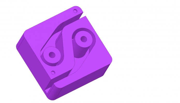
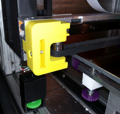
I have just about finished the XY stage design and will be building it shortly. I'll be using 22 mm diameter F608ZZ bearings for the idlers, and designed a self-locking belt clamp for the extruder carriage.
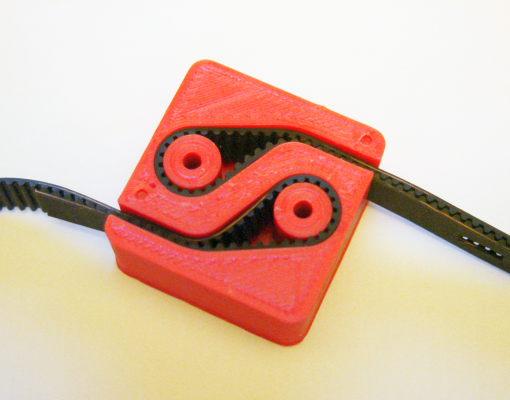
The belt clamp has to keep the belt(s) parallel to the X axis throughout the range of motion, so I laid out the clamp to do just that. The small holes in the top indicate the where the smooth side of the belt enters the clamp. There will be two of these clamps stacked on top of each other, one for each belt.
I printed it and checked the fit- perfect! GT2 belt is 1.38 mm thick. When you interdigitate the teeth by folding the belt, the thickness becomes 2.2 mm. The clamp has 2.2 mm slots that don't allow the belt teeth any room to slide over each other. The blocks will be glued together and the holes in the posts will be used to mount them on the extruder carriage. The belt tension will be trying to make the block twist, but the other block will twist the other direction. Once the two blocks are glued together, the equal and opposite torques will cancel and twisting force will be minimal.
Ultra MegaMax Dominator 3D printer: [drmrehorst.blogspot.com]
|
Re: My coreXY design is progressing to the build stage May 04, 2016 02:28PM |
Registered: 11 years ago Posts: 1,049 |
Nice DD
Really like how Top circuit cancels out Bottom circuit twisting torque.
Is tension on top/bottom applied at the same time?
(Appears you will be using two level belt system)
Got parts piling up here for my build
15mm 500mm glide rail for X
12mm 400mm glides for other axes
belts, pulleys, motors
Basement elves just won't assemble it

|
Re: My coreXY design is progressing to the build stage May 04, 2016 03:08PM |
Registered: 11 years ago Posts: 5,780 |
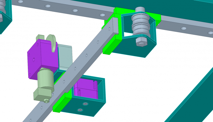
Yes, two-level belts. Attempting to set approximately equal tension on both belts at the same time might require me to grow and extra arm or two. It's OK- the screws will attach the belt clamps to the inside of a rectangular aluminum tube and prevent it from going anywhere. I'll countersink the holes to force the screws to center themselves in the holes.
Ultra MegaMax Dominator 3D printer: [drmrehorst.blogspot.com]
Ultra MegaMax Dominator 3D printer: [drmrehorst.blogspot.com]
|
Re: My coreXY design is progressing to the build stage May 04, 2016 11:05PM |
Registered: 11 years ago Posts: 1,049 |
|
Re: My coreXY design is progressing to the build stage May 05, 2016 03:09AM |
Registered: 8 years ago Posts: 776 |
Quote
the_digital_dentist
I have just about finished the XY stage design and will be building it shortly. I'll be using 22 mm diameter F608ZZ bearings for the idlers, and designed a self-locking belt clamp for the extruder carriage.
The belt clamp has to keep the belt(s) parallel to the X axis throughout the range of motion, so I laid out the clamp to do just that. The small holes in the top indicate the where the smooth side of the belt enters the clamp. There will be two of these clamps stacked on top of each other, one for each belt.
niiice. i like how they clamp together so no need for tensioning etc. etc. oo, it's got me thinking. how about putting (either a real or) a GT2 gear in the centre and wrapping the belt around it then clamping that down? you could then change the tension on an resolution greater than a single belt-tooth. alsooo... not using a GT2 but just a circular spinning bit of plastic... you miiight be able to put the two belts back-to-back in double spirals (so they lock one against the other) and then similarly tension them up.
the arrangement would be pretty much exactly like one of those retractable laptop mice USB cables:
wouldn't need bearings...
but... thinking about it, i do like the simplicity of what you came up with...
|
Re: My coreXY design is progressing to the build stage May 05, 2016 08:29AM |
Registered: 9 years ago Posts: 1,035 |
Will you be using the same guides for Z? If not then what will you use?
RepRap Lander concept on Concept Forge
RepRap Lander concept on RepRap Forums
My Things, mostly experimental stuff
RepRap Lander concept on Concept Forge
RepRap Lander concept on RepRap Forums
My Things, mostly experimental stuff
|
Re: My coreXY design is progressing to the build stage May 05, 2016 12:36PM |
Registered: 11 years ago Posts: 5,780 |
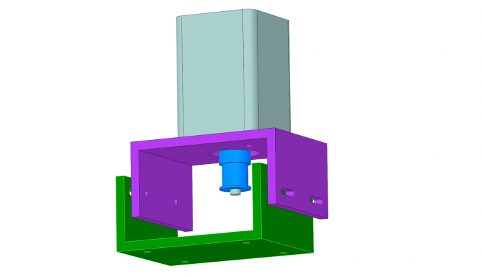
The green parts are bearing blocks on linear guides, not printed.
The Y axis linear guides will be screwed to a flat plate. The X axis guide will be end supported.
DesignSpark Mechanical
Ultra MegaMax Dominator 3D printer: [drmrehorst.blogspot.com]
The Y axis linear guides will be screwed to a flat plate. The X axis guide will be end supported.
DesignSpark Mechanical
Quote
cozmicray
Printed parts - the green brackets ?
I thought that was a no-no (all metal)
Guide rails are not going to be mounted to any support?
What CAD SW do you use?
Ultra MegaMax Dominator 3D printer: [drmrehorst.blogspot.com]
|
Re: My coreXY design is progressing to the build stage May 05, 2016 12:43PM |
Registered: 11 years ago Posts: 5,780 |
In the scheme you're talking about, you need some sort of ratchet mechanism (or very strong spring) to maintain the tension. It gets mechanically complex pretty quickly. I thought about doing something like that but decided it is easier to tension belts by sliding the motor mounts.
I considered some sort of sliding mechanism where you tension the belts with screws, but again, it gets too big and complex without offering any real benefit. O course, maybe I just haven't figured out the right way to do it...
Ultra MegaMax Dominator 3D printer: [drmrehorst.blogspot.com]
I considered some sort of sliding mechanism where you tension the belts with screws, but again, it gets too big and complex without offering any real benefit. O course, maybe I just haven't figured out the right way to do it...
Quote
lkcl
niiice. i like how they clamp together so no need for tensioning etc. etc. oo, it's got me thinking. how about putting (either a real or) a GT2 gear in the centre and wrapping the belt around it then clamping that down? you could then change the tension on an resolution greater than a single belt-tooth. alsooo... not using a GT2 but just a circular spinning bit of plastic... you miiight be able to put the two belts back-to-back in double spirals (so they lock one against the other) and then similarly tension them up.
the arrangement would be pretty much exactly like one of those retractable laptop mice USB cables:
[attachment 77566 images.jpeg]
wouldn't need bearings...
but... thinking about it, i do like the simplicity of what you came up with...
Ultra MegaMax Dominator 3D printer: [drmrehorst.blogspot.com]
|
Re: My coreXY design is progressing to the build stage May 05, 2016 12:44PM |
Registered: 11 years ago Posts: 5,780 |
Quote
realthor
Will you be using the same guides for Z? If not then what will you use?
Definitely linear guides for the Z axis...
Ultra MegaMax Dominator 3D printer: [drmrehorst.blogspot.com]
|
Re: My coreXY design is progressing to the build stage May 05, 2016 01:07PM |
Registered: 10 years ago Posts: 651 |
|
Re: My coreXY design is progressing to the build stage May 05, 2016 01:59PM |
Registered: 11 years ago Posts: 5,780 |
The X axis linear guide is 24 mm wide x 8 mm thick. I'm not too concerned about sagging, but if it proves to be a problem, I'll add an aluminum support tube.
Static behavior is one thing, dynamic effects are something else. When the Y axis accelerates, the mass of the X axis guide and extruder carriage will resist which will lead to some wobble in the Y axis due to the flexing of the X axis linear guide. I expect to operate this machine at 2000 mm/sec^2 acceleration. That's about 1/5 of 1 G, so meh. I don't think it will be a problem unless there's some resonance that gets excited by the motion. I don't have any way to calculate that so I'll try it and see if it works OK.
Ultra MegaMax Dominator 3D printer: [drmrehorst.blogspot.com]
|
Re: My coreXY design is progressing to the build stage May 07, 2016 07:25PM |
Registered: 8 years ago Posts: 776 |
Quote
the_digital_dentist
In the scheme you're talking about, you need some sort of ratchet mechanism (or very strong spring) to maintain the tension.
oh, no - i was just thinking something you could tighten and hold in place by hand until you'd screwed down a bolt through the middle.
Quote
I considered some sort of sliding mechanism where you tension the belts with screws, but again, it gets too big and complex without offering any real benefit. O course, maybe I just haven't figured out the right way to do it...
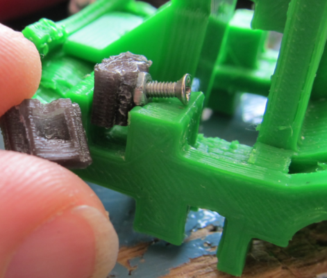
you saw how i did the sandwich200 v1 carriage, right? mmm... picturepicturepicture... ah ha!
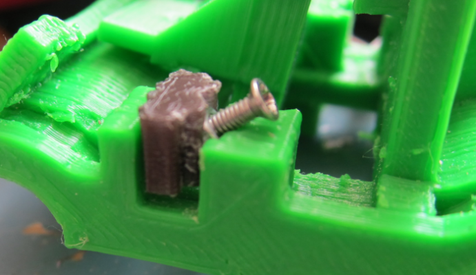
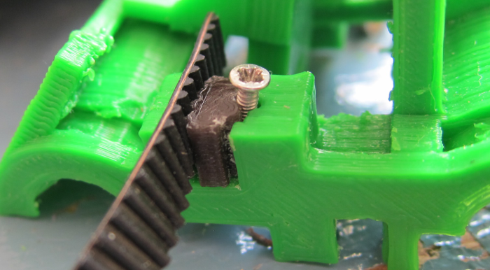
those are M2x5mm nut and bolt sets, you lay them flat with the nut half-way in, push the black/translucent "gnasher" down, and the M2x5 bolt pops upright as the nut is taken down with the gnasher. you can then drop the belt in and out (one tooth at a time), check the tension, and, when you're ready, just tighten up the M2x5 bolt GENTLY until it starts to go between the "gnasher" and the wall, and it pushes the gnasher against the belt, squashing it and holding everything in place. the nice thing is, if the belt thickness varies (which it does depending on supplier) that doesn't matter.
i have to admit i *really* don't like the idea of tensioning up by moving the motors. how can you get the motor to sit perfectly still whilst you tighten up the motor holding screws? you can't. the fact that the screws are loose enough so you can move them [to the right place] means that the motor will be pulled off-vertical. by the time you've tightened them up, it's either moved or it's not exactly in the position you *thought* it was when you tested the tension.... eugh
 no don't tell me - all the ways i can think of are horribly fiddly.
|
Re: My coreXY design is progressing to the build stage May 07, 2016 08:46PM |
Registered: 11 years ago Posts: 5,780 |
Thanks, but I can't quite match your description to the picture.
I think I'll be able to design and fabricate a motor mount that will work. The tension on the belt doesn't need to be like a guitar sting- you can easily pull it tight enough with one hand and tighten screws with the other. If that isn't enough tension for some reason, a screw that pulls on the motor will certainly do the job.
Ultra MegaMax Dominator 3D printer: [drmrehorst.blogspot.com]
|
Anonymous User
Re: My coreXY design is progressing to the build stage May 08, 2016 12:53AM |
Quote
the_digital_dentist
Thanks, but I can't quite match your description to the picture.
I think I'll be able to design and fabricate a motor mount that will work. The tension on the belt doesn't need to be like a guitar sting- you can easily pull it tight enough with one hand and tighten screws with the other. If that isn't enough tension for some reason, a screw that pulls on the motor will certainly do the job.
In your case, it is good engineering practice to tension the belt by moving the motor as it simplifies the design, eliminating the need for idler pulleys. A simple bracket or even no bracket at all, just slots for the mounting screws, eventually one an eccentric bolt. Plenty of example around, office printers, cars, lathe .....
PS: I managed to "match". Not good, cumbersome and you don't tension a belt one tooth at a time.
|
Re: My coreXY design is progressing to the build stage May 08, 2016 12:51PM |
Registered: 8 years ago Posts: 776 |
Quote
the_digital_dentist
Thanks, but I can't quite match your description to the picture.
hmm, sorry, let me add some in-between pictures. first one: an uninstalled gnasher on the left, you can see an indentation: this is what takes the M2 nut. just over the top of the indentation is a semi-circular cut-out which fits round the M2 bolt. so. on the right: gnasher being installed. drop M2x5 bolt and nut into gap, at roughly 80 to 75 degrees. nut goes into gnasher indentation:
begin pushing gnasher down. M2x5 bolt pops upright to 45 degrees as the indentation catches the nut.
just before last phase: install belt. it's slightly easier at this phase. M2x5 bolt is almost upright. nut is no longer visible as it's entirely inside the gnasher's indentation.
the last phase is: tighten up the M2x5 bolt. nut raises up, catches against inside of indentation. with nowhere else to go, M2x5 bolt must go DOWN. as it goes DOWN it forces its way BETWEEN the gnasher and the carriage, thus pushing them apart.
as it pushes the gnasher apart, gnasher chomps against the belt. job done.
Quote
I think I'll be able to design and fabricate a motor mount that will work. The tension on the belt doesn't need to be like a guitar sting- you can easily pull it tight enough with one hand and tighten screws with the other. If that isn't enough tension for some reason, a screw that pulls on the motor will certainly do the job.
that would probably do it - and with a few trial-and-error iterations on tensioning it would work. once set up you'd be able to leave it, so it's no huge deal. nice thing about the idea you had, you could tension up the motor holding bolts to the point where they could potentially still move... but not by hand... and then use the "screw that pulls on the motor" to overcome that resistance. this would overcome the objection i had about the motor holding bolts being so loose that the motor would be at an oblique angle, resulting in a change in belt-tension *as* you tightened them up. personally i wouldn't choose this type of tension adjustment unless forced to by other factors (such as i am now for the sandwich200v2 z axis motor. oh well...)
|
Re: My coreXY design is progressing to the build stage May 08, 2016 02:17PM |
Registered: 11 years ago Posts: 1,049 |
ikcl
by the state of your phillips bolt head
time for a proper phillips screw driver
or use hex (allen) head bolt
oh --- I know kitchen utensils used
your Timing belt jam --- kluge at best
why not

by the state of your phillips bolt head
time for a proper phillips screw driver
or use hex (allen) head bolt
oh --- I know kitchen utensils used
your Timing belt jam --- kluge at best
why not

|
Re: My coreXY design is progressing to the build stage May 08, 2016 02:27PM |
Registered: 11 years ago Posts: 5,780 |
Ikcl,
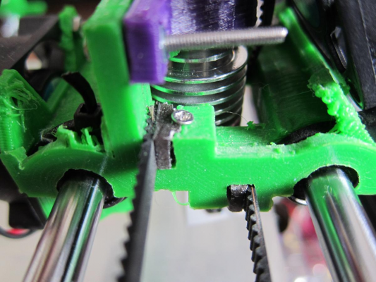
Hmmm. You have to manually position the belt to use this clamp to also tension the belt. That's a tricky thing to do. This is the belt clamp on my current printer: Belt Clamp which is a smaller version of the thing I designed for the coreXY. I suppose I could manually pull at the belt and tension it using the clamp the same way your clamp does, except that I don't need any tools to do it. It might be pretty hard to achieve reasonable tension that way.
This is the current, 3D printed X axis belt tensioner, soon to be replaced by aluminum:
I am thinking I'll make the motor mount in two pieces that fit together, a fixed piece screwed to the base plate, and a sliding piece that screws to the motor. The two pieces will fit together with tongues and grooves that will constrain the motor's motion to sliding and not tilting.
Edited 1 time(s). Last edit at 05/08/2016 02:29PM by the_digital_dentist.
Ultra MegaMax Dominator 3D printer: [drmrehorst.blogspot.com]
|
Re: My coreXY design is progressing to the build stage May 08, 2016 04:55PM |
Registered: 8 years ago Posts: 776 |
Quote
cozmicray
ikcl
by the state of your phillips bolt head
time for a proper phillips screw driver
or use hex (allen) head bolt
yeahman - i knoww.... but have you tried ordering M2 bolts from a hardware store? maaan they're hard to get. i happened to have some (from the libre laptop, for the LCD edge) so used those. that one was one i threw out, i just used it to do the picture for dd. tiny screws, they get wrecked pretty quick if you're disassembling things 10-15 times like i have been for the libre laptop
Quote
oh --- I know kitchen utensils used
don't laugh, but i really do use teaspoons and kitchen knives! i use them for bowden tubes - kitchen knives have this great thing where they start off thin (on the top blunt edge) and then become thicker. you can push them between the bowden tube end-clamp at the thin bit then slide them along to lift it up

Quote
your Timing belt jam --- kluge at best
why not
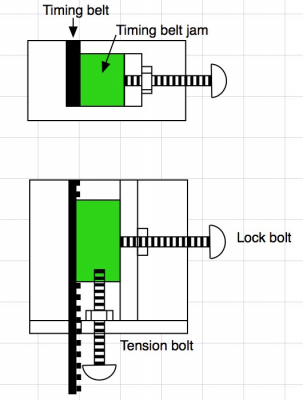
[attachment 77731 Belt_jam.jpg]
i love it! that's much better..... oh wait.... hang on - that nut will be sticking out, won't it? which means it would hit the X-end. i've reduced the width of this printer down to 312mm. clearance left and right is *three* (3) millimetres from where the hotend reaches one edge of the 214x214 printbed to the other edge. so i love it... but can't use it. bleh. maybe for a future printer. or i'll think about a way to turn the belt through 90 degrees so the screw goes sideways, ahhhh yeahhhh, that would work: the tensioner screw would then be at 90 degrees to the x-end and would not stick out.
|
Re: My coreXY design is progressing to the build stage May 08, 2016 05:06PM |
Registered: 8 years ago Posts: 776 |
Quote
the_digital_dentist
Ikcl,
Hmmm. You have to manually position the belt to use this clamp to also tension the belt.
one notch at a time. ok the first 2 you can just drop in and leave them there. then you go "pungg" on the belts - i know cozmicray will shudder at that, and ask us to get out the force guage...
 - then pop the belt out, keep your fingers on it so you know where it was, move it up by one (or two) notches... tighten the screw back up... not too much. doesn't have to be completely locked down to at least hold the belt in place, it's rubber, it compresses, so even just loose on the screw the belt still stays in
Quote
That's a tricky thing to do.
not having anything else to compare it against (except the original Fusebox, and the mendel90, which are both radically different) i found the process quite straightforward. except for the times where i dropped the bloody M2x5 bolts because i loosened them too much... argh....

Quote
This is the belt clamp on my current printer: Belt Clamp which is a smaller version of the thing I designed for the coreXY. I suppose I could manually pull at the belt and tension it using the clamp the same way your clamp does, except that I don't need any tools to do it. It might be pretty hard to achieve reasonable tension that way.
i like that tensioning design - it pulls the entire set of bearings, right? no the design i did, you're tensioning one notch at a time, which i found to be good enough - that's 2mm. so you can just count up 1 notch, it's much more straightforward than it looks. with a motor-on-screws-that-move, you have *no idea* if you changed the tension accidentally during tightening up the screws, which is why i liked that idea you had of using a sideways screw (just like the picture above that cozmicray did) to move the entire motor assembly along, very accurately. just like you've got in that picture, except the motor mounted on the moving-bit.
Quote
I am thinking I'll make the motor mount in two pieces that fit together, a fixed piece screwed to the base plate, and a sliding piece that screws to the motor. The two pieces will fit together with tongues and grooves that will constrain the motor's motion to sliding and not tilting.
great. honestly, sounds perfect. especially if it's in aluminium. really must do a CNC next.
Edited 1 time(s). Last edit at 05/08/2016 05:07PM by lkcl.
|
Re: My coreXY design is progressing to the build stage May 08, 2016 05:27PM |
Registered: 11 years ago Posts: 5,780 |
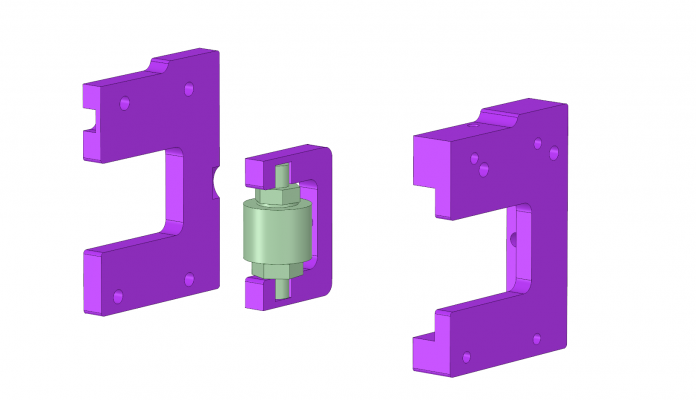
Here's a quick idea for a sliding motor mount that requires minimal machining/cutting/drilling and uses two identically processed pieces of off-the-shelf C channel stock:
It isn't as small as it could be if you machined the whole thing, but it sure is easy and I have no doubt about its rigidity and stability. As designed it will suck up 20 mm of belt length which is a LOT more than it should ever have to.
Since its all aluminum it will transfer heat from the motor to the larger base plate, too, unlike printed designs.
The belt tensioner uses the countersunk screw on the left side to pull a U-shaped piece that holds the axle of the pulley. You can continuously adjust belt tension with it, about 16 mm of slack can be taken up, far more than necessary. You can see in the picture that the belt is riding low on the pulleys- that's because the belt tension is causing the plastic to flex and tilting the pulley's axle a little. That's why I am going to convert to aluminum. Here's the aluminum version exploded:
Edited 1 time(s). Last edit at 05/08/2016 05:36PM by the_digital_dentist.
Ultra MegaMax Dominator 3D printer: [drmrehorst.blogspot.com]
|
Anonymous User
Re: My coreXY design is progressing to the build stage May 08, 2016 07:32PM |
|
Anonymous User
Re: My coreXY design is progressing to the build stage May 08, 2016 07:37PM |
Quote
cozmicray
ikcl
by the state of your phillips bolt head
time for a proper phillips screw driver
or use hex (allen) head bolt
oh --- I know kitchen utensils used
From the CSI report, it is a Pozidriv that has been badly abused by a Phillips bit !
 Or maybe a Japanese JIS ?
Edited 1 time(s). Last edit at 05/08/2016 07:38PM by MKSA.
|
Re: My coreXY design is progressing to the build stage May 08, 2016 11:29PM |
Registered: 10 years ago Posts: 651 |
Quote
the_digital_dentist
I am thinking I'll make the motor mount in two pieces that fit together, a fixed piece screwed to the base plate, and a sliding piece that screws to the motor. The two pieces will fit together with tongues and grooves that will constrain the motor's motion to sliding and not tilting.
This is exactly how I've designed mine too. Imagine Son of Megamax's X-Idler, but moves the entire Motor, is adjustable via a screw, also has the tongue and groove sliding mechanism, and also has elongated holes which would be used to lock down the sliding mechanism.
|
Re: My coreXY design is progressing to the build stage May 09, 2016 04:50AM |
Registered: 8 years ago Posts: 776 |
|
Re: My coreXY design is progressing to the build stage May 09, 2016 07:35AM |
Registered: 11 years ago Posts: 5,780 |
I'll probably use DSP drivers for the XY mechanism like the ones in the X and Y axes in my current printer. It uses a NEMA-23 motors and the only noise the X axis makes is a quiet hissing while it is running. The screw driven Y axis is pretty noisy, but I attribute that to motor vibration coupled via the drive screw to the bed plate. Screws are very efficient at transmitting vibration and noise.
NEMA-17 motors are typically a lot quieter than NEMA-23 motors so I don't expect noise to be an issue. We'll see.
Ultra MegaMax Dominator 3D printer: [drmrehorst.blogspot.com]
NEMA-17 motors are typically a lot quieter than NEMA-23 motors so I don't expect noise to be an issue. We'll see.
Ultra MegaMax Dominator 3D printer: [drmrehorst.blogspot.com]
|
Re: My coreXY design is progressing to the build stage May 09, 2016 01:22PM |
Registered: 8 years ago Posts: 776 |
|
Re: My coreXY design is progressing to the build stage May 09, 2016 06:34PM |
Registered: 10 years ago Posts: 14,672 |
Any particular reason why you want to shell out on DSP drivers, when you are using Nema17 motors? Sounds like possible overkill to me.
Large delta printer [miscsolutions.wordpress.com], E3D tool changer, Robotdigg SCARA printer, Crane Quad and Ormerod
Disclosure: I design Duet electronics and work on RepRapFirmware, [duet3d.com].
Large delta printer [miscsolutions.wordpress.com], E3D tool changer, Robotdigg SCARA printer, Crane Quad and Ormerod
Disclosure: I design Duet electronics and work on RepRapFirmware, [duet3d.com].
|
Re: My coreXY design is progressing to the build stage May 09, 2016 09:02PM |
Registered: 11 years ago Posts: 5,780 |
Low noise, and high voltage operation. I'll be making a power supply for the motors, too. There's no kill like overkill!
Ultra MegaMax Dominator 3D printer: [drmrehorst.blogspot.com]
Ultra MegaMax Dominator 3D printer: [drmrehorst.blogspot.com]
|
Re: My coreXY design is progressing to the build stage May 10, 2016 02:38AM |
Registered: 10 years ago Posts: 14,672 |
Low noise I understand, although there are less expensive ways of achieving that. High voltage I don't, unless you are looking for insanely high travel speeds. Even with 0.9deg Nema 17 motors, my delta achieves more than 300mm/sec travel speed using 24V power. A CoreXY design using the same motors should achieve nearly 500mm/sec, or double that using 1.8deg motors.
Large delta printer [miscsolutions.wordpress.com], E3D tool changer, Robotdigg SCARA printer, Crane Quad and Ormerod
Disclosure: I design Duet electronics and work on RepRapFirmware, [duet3d.com].
Large delta printer [miscsolutions.wordpress.com], E3D tool changer, Robotdigg SCARA printer, Crane Quad and Ormerod
Disclosure: I design Duet electronics and work on RepRapFirmware, [duet3d.com].
|
Re: My coreXY design is progressing to the build stage May 10, 2016 12:12PM |
Registered: 11 years ago Posts: 5,780 |
Sorry, only registered users may post in this forum.
