i3 Video Build Log
Posted by ikilledkenny
|
Re: i3 Video Build Log March 17, 2013 04:37PM |
Registered: 13 years ago Posts: 248 |
That's a time saving tracing feature in Inkscape. I must give that a go.
Nice practical tutorial. I enjoyed it. It was useful.
[numbersixreprap.blogspot.com]
Nice practical tutorial. I enjoyed it. It was useful.
[numbersixreprap.blogspot.com]
|
Re: i3 Video Build Log March 31, 2013 11:05AM |
Registered: 11 years ago Posts: 41 |
im 95% through my build of an aluminum prusa i3. i modified it for m10 threaded rod on the y axis, m8 smooth rod and lm8uus. ive designed the x carriage bracket for a budaschnozzle/ wades extruder. i am using a RAMBo Board, repetier host and repetier firmware. i just calibrated yesterday, pics coming soon!
|
Re: i3 Video Build Log April 02, 2013 07:45PM |
Registered: 12 years ago Posts: 99 |
|
Re: i3 Video Build Log April 10, 2013 06:08PM |
Registered: 11 years ago Posts: 22 |
thainfamousnate Wrote:
-------------------------------------------------------
> im 95% through my build of an aluminum prusa i3. i
> modified it for m10 threaded rod on the y axis, m8
> smooth rod and lm8uus. ive designed the x carriage
> bracket for a budaschnozzle/ wades extruder. i am
> using a RAMBo Board, repetier host and repetier
> firmware. i just calibrated yesterday, pics coming
> soon!
I'll be interested to see more about this. I'm also building an i3 and considering a Budaschnozzle with Wade's extruder.
|
Re: i3 Video Build Log April 19, 2013 03:44PM |
Registered: 11 years ago Posts: 22 |
|
Re: i3 Video Build Log April 20, 2013 02:30PM |
Registered: 11 years ago Posts: 89 |
|
Re: i3 Video Build Log April 20, 2013 03:21PM |
Registered: 12 years ago Posts: 972 |
|
Re: i3 Video Build Log April 20, 2013 03:32PM |
Registered: 11 years ago Posts: 22 |
SheldonE Wrote:
-------------------------------------------------------
> Just a heads up, the BOM for the i3 seems to be
> out of date. It mentions 2xM10 threaded rods for
> the Y-axis, but the Y corners can only take an M8
> rod. I updated the Wiki accordingly.
>
> Does anyone know if the M5 threaded rods for the
> Z-axis are still used?
The EiNSTeiN Variant takes 10mm threaded rods for the Y corners. See the plastic parts referred to on the build manual:
[reprap.org]
M5 appears to be still in use for the Z axis. M5 is close in diameter to the motor shafts. And the thread is finer than larger rod, which helps with accurate layer height.
My (rarely updated) Prusa i3 build log: [3dtheorist.wordpress.com]
|
Re: i3 Video Build Log April 24, 2013 08:27AM |
Registered: 11 years ago Posts: 64 |
Hi SheldonE,
I hope you don't mind, but I've changed the wikipage back to M10. Both the EiNSTeiN and the "official" Prusa versions use M10 for the long threaded rods now and having the wiki mention M8 might add to the ever growing confusion surrounding all the i3 variations . If you happen to have y-corners that take M8, you might have printed parts from a much older revision of either version.
I hope you don't mind, but I've changed the wikipage back to M10. Both the EiNSTeiN and the "official" Prusa versions use M10 for the long threaded rods now and having the wiki mention M8 might add to the ever growing confusion surrounding all the i3 variations
. If you happen to have y-corners that take M8, you might have printed parts from a much older revision of either version.
|
Re: i3 Video Build Log April 24, 2013 03:27PM |
Registered: 11 years ago Posts: 89 |
jcr Wrote:
-------------------------------------------------------
> surrounding all the i3 variations. If you
> happen to have y-corners that take M8, you might
> have printed parts from a much older revision of
> either version.
As far as I know, my parts came from the github repository linked on the main i3 page here. The Y-axis corners definitely have 8mm holes.
-------------------------------------------------------
> surrounding all the i3 variations
. If you> happen to have y-corners that take M8, you might
> have printed parts from a much older revision of
> either version.
As far as I know, my parts came from the github repository linked on the main i3 page here. The Y-axis corners definitely have 8mm holes.
|
Re: i3 Video Build Log April 24, 2013 03:38PM |
Registered: 12 years ago Posts: 972 |
|
Re: i3 Video Build Log April 25, 2013 04:33AM |
Registered: 11 years ago Posts: 64 |
Both the single_plate and box_frame y-corners from Josef's repo use the M8/M10 combination now and already have for some time. But somehow people keep churning out parts from older revisions that still use the M8 holes for the longer threaded rods, leaving quite a number of people confused after having bought parts from Ebay
As a side note, the box_frame parts can be used for single frame builds too now, provided you set i_am_box to 0 in the config. As this seems to be the only version that sees active development, perhaps the original single plate parts could be considered depricated, even though those remain perfectly usable of course. Or maybe they're just "done"
As a side note, the box_frame parts can be used for single frame builds too now, provided you set i_am_box to 0 in the config. As this seems to be the only version that sees active development, perhaps the original single plate parts could be considered depricated, even though those remain perfectly usable of course. Or maybe they're just "done"
|
Re: i3 Video Build Log April 25, 2013 07:24PM |
Registered: 11 years ago Posts: 89 |
|
Re: i3 Video Build Log April 26, 2013 03:13AM |
Registered: 11 years ago Posts: 64 |
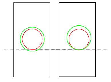
I've heard of people doing so, but depending on the frame that you're using you might run into clearance issues. When you're drilling to 10mm exactly centred on the 8mm hole, the bottom of the M10 threaded rod will be 1mm closer to the surface the printer is sitting on. In case of a box frame that probably will result in the y-corners getting lifted from whatever surface your printer is sitting on. Ideally you want to keep the bottom of the hole at the same level. See my beautiful artist's impression of what I mean attached
|
Re: i3 Video Build Log April 26, 2013 04:38AM |
Registered: 11 years ago Posts: 89 |
|
Re: i3 Video Build Log April 26, 2013 12:06PM |
Registered: 11 years ago Posts: 22 |
If you have a router, you could also shave down the wood where the Y axis attaches to it.
My (rarely updated) Prusa i3 build log: [3dtheorist.wordpress.com]
My (rarely updated) Prusa i3 build log: [3dtheorist.wordpress.com]
|
Re: i3 Video Build Log April 27, 2013 01:46AM |
Registered: 11 years ago Posts: 89 |
Just in case anyone hits the same hurdle, drilling the hole out to 10mm works, but go very slowly. I drilled one a bit to fast and it cracked (delaminated):
I'm hoping it'll hold out until I can print off some new feet. Here's my Y-frame:
Edited 1 time(s). Last edit at 04/27/2013 01:49AM by SheldonE.

I'm hoping it'll hold out until I can print off some new feet. Here's my Y-frame:

Edited 1 time(s). Last edit at 04/27/2013 01:49AM by SheldonE.
|
Re: i3 Video Build Log April 30, 2013 01:32PM |
Registered: 12 years ago Posts: 99 |
I need to update some of the videos to put a big WARNING up. I started this blog back prior to the STL's being publicly available. A lot has changed since I started (first iterations where smaller, why I labeled mine XL. The recent iteration is now slightly taller then mine, oh well lol.
Another change over time was the use of M10. My design does use 5/16 threaded rod (close to M8). Since I started the stock design has been upgraded to M10. M8 or 5/16 will still work (and I think is an option in the openscad model), but will not be as ridged.
SheldonE - Nice work so far!!! I have had lamination issues also when trying to drill out parts too fast. I found what works well is to SLOWLY step up in drill size, and use a vice/drill press if possible. To fix the lamination issue throw some super glue in the crack and compress the part with a clamp, I have had good results doing this.
Thanks all again for your comments! If there are other videos/tutorials would would like me to do let me know.
|
Re: i3 Video Build Log April 30, 2013 07:03PM |
Registered: 11 years ago Posts: 89 |
ikilledkenny Wrote:
-------------------------------------------------------
> SheldonE - Nice work so far!!!
Thanks, but I suspect this is the easy part. My woodworking skills really suck, I can't cut a straight line for nuts. I'm also building an XL version, I should have around 400mm of Y-axis and I'm planing similar measurements for the X ans Z axes.
|
Re: i3 Video Build Log May 02, 2013 01:26PM |
Registered: 12 years ago Posts: 99 |
What are you using for a print bed?
I can't stress it enough but if you are doing the box method make sure EVERYTHING is square. The first box I did was all over the place and produced nothing but issues. Some suggestions;
Have your local big box cut the boards if possible. Most places will cut them to length for you if you are buying the wood.
Purchase a square, and if able get some 90deg corner clamps. The 90 deg corner clamps helped out A LOT.
If using a table saw cut boards of equal length all at once. This will make sure everything is equal length that should be.
Cut boards as you go. This requires some planning ahead of time, but it helps to make sure parts fit in the event some cuts are a bit off.
Pre-drill all the holes, this helps prevent splitting
Test fit, Test fit, Test fit before fastening.
|
Re: i3 Video Build Log May 02, 2013 08:22PM |
Registered: 11 years ago Posts: 89 |
ikilledkenny Wrote:
-------------------------------------------------------
> What are you using for a print bed?
Yeah, haven't gotten that far yet, I'm still collecting parts, but it'll probably be MDF. I can't really afford to buy them all the parts at once. I'll be getting the last of my vitamins next pay and I'll start on the box the pay after.
> I can't stress it enough but if you are doing the
> box method make sure EVERYTHING is square. The
> first box I did was all over the place and
> produced nothing but issues. Some suggestions;
Yeah, I watched you're video blog and noticed you skipped a few steps in the middle somewhere.
> Have your local big box cut the boards if
> possible. Most places will cut them to length for
> you if you are buying the wood.
We don't have Bix Box in Australia and our local hardware stores (Bunnings) will only do one or 2 cuts for free.
> Purchase a square, and if able get some 90deg
> corner clamps. The 90 deg corner clamps helped
> out A LOT.
Yep, corner squares are on the list of things to buy for the box. I already have 2 squares.
> If using a table saw cut boards of equal length
> all at once. This will make sure everything is
> equal length that should be.
Yeah, I think it'll be a good old fashioned hand saw and some dead reckoning. *shudder*
> Pre-drill all the holes, this helps prevent
> splitting
Yep
> Test fit, Test fit, Test fit before fastening.
Yep, thanks for the advice.
|
Re: i3 Video Build Log May 30, 2013 07:10AM |
Registered: 12 years ago Posts: 99 |
New video out - [www.youtube.com]
Tutorial on how to split up the g-code into two separate print files as well as some more g-code definitions.
Tutorial on how to split up the g-code into two separate print files as well as some more g-code definitions.

Sorry, only registered users may post in this forum.