Home
>
Reprappers
>
Topic
25% done
Posted by mikefazz
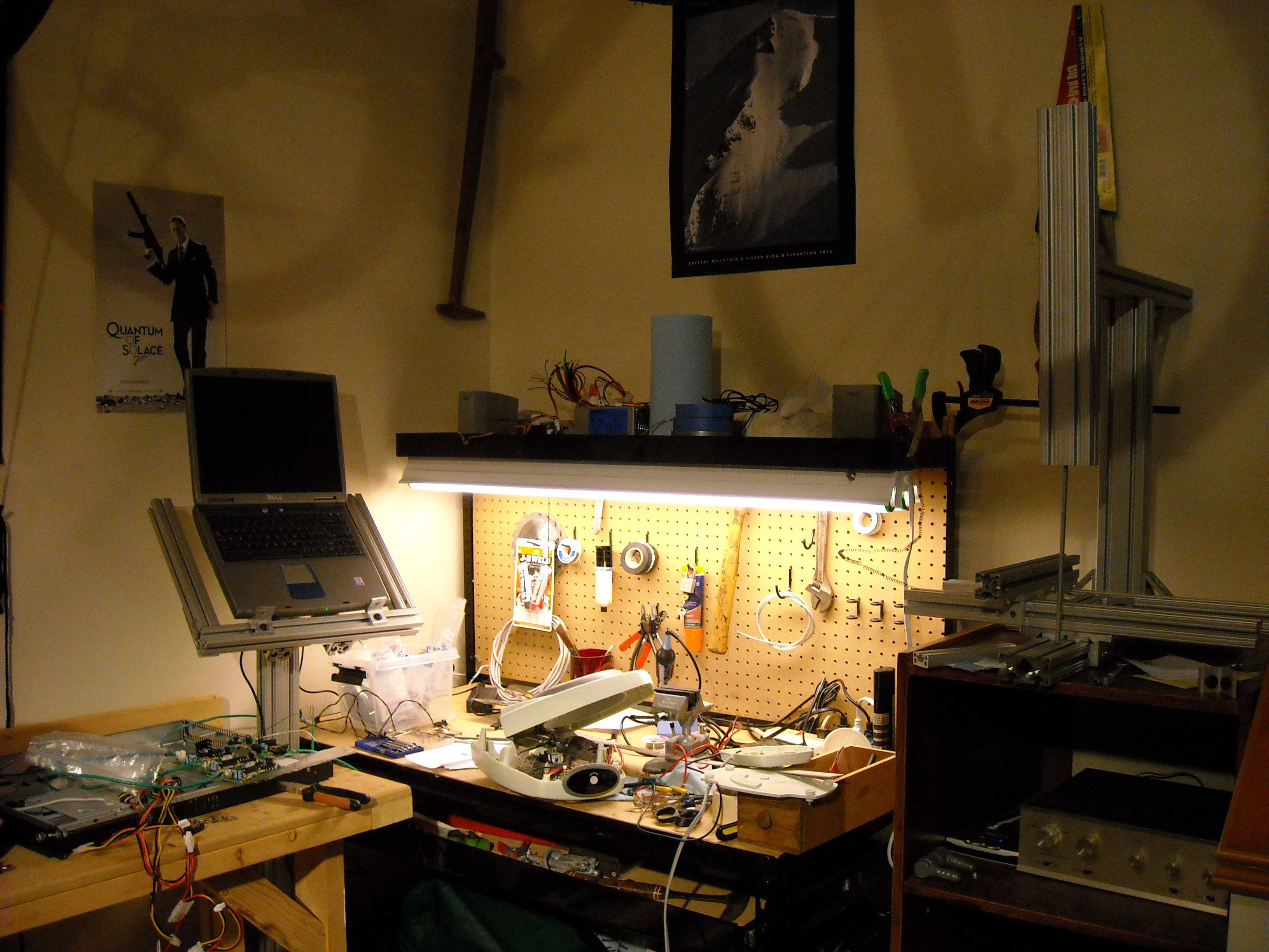
So I have begun some real work on my RepStrap. In the picture you can see the mess of progress.
I have the following:
- Most of the main frame in 80/20, I will see if I can get those bearings to work (cross my fingers). It follows the knee mill setup.
- I have all the PCB's put together though waiting for a couple of missing components
- I am planning to put all the electronics in a server rack I got at a used PC part store. This allows contained cooling as well as an integrated power supply. It also looks cool
- I hope to use a 'pinch wheel' filament extruder. I just don't like the present extruder design ...
...
- You may also notice the electric heater I partially took apart. I am going to try to use the inside heating element... we'll see.
Well I got a fair bit left to keep me busy before I need to buy the rest of the parts


I have the following:
- Most of the main frame in 80/20, I will see if I can get those bearings to work (cross my fingers). It follows the knee mill setup.
- I have all the PCB's put together though waiting for a couple of missing components
- I am planning to put all the electronics in a server rack I got at a used PC part store. This allows contained cooling as well as an integrated power supply. It also looks cool
- I hope to use a 'pinch wheel' filament extruder. I just don't like the present extruder design
...- You may also notice the electric heater I partially took apart. I am going to try to use the inside heating element... we'll see.
Well I got a fair bit left to keep me busy before I need to buy the rest of the parts
|
Re: 25% done December 21, 2008 10:38PM |
Registered: 15 years ago Posts: 88 |
Good luck, it looks like you're well on your way.. you may need to redesign the lowest stage there, though. I've messed around with those 8020 UHMW bearings before, and they have significant issues with binding under a cantilevered force.. it may not be an issue in this case (the double-wide/1020 size was a good choice), but I would expect that you're going to see a lot more friction when the stage it supports is at maximum travel in either direction than when it's centered... Ideally, you'd have a bearing underneath it at the edges of it's travel, not the center.
What are you using to drive your XY stage? (ie threaded rod, timing belt?)
What are you using to drive your XY stage? (ie threaded rod, timing belt?)
|
Re: 25% done December 21, 2008 10:44PM |
Registered: 15 years ago Posts: 300 |
Would love to see your mechanics when you get to them. Interesting approach for holding the electronics!
I never though of mounting the pins for Sanguino on the top of the board! Though since there is now a breakout shield they need to be on the bottom.
Rumors are (mentioned in the upcoming lcd controller) that there is a Motherboard sheild coming which I think is going to require some re-wiring since they are looking at I2C and that conflicts (IMHO) with the Z-stage wiring.
But hey all the ribbon cables that we are seeing with the new revisions of the boards will probally just plug in!
Hey Zach how about a peek at the new mappings for Sanguino?
|
Re: 25% done December 22, 2008 12:25AM |
Registered: 15 years ago Posts: 153 |
|
Re: 25% done December 23, 2008 06:38PM |
Registered: 15 years ago Posts: 37 |
Ah thanks for all the input
Corwin:
Yeah I looked around online and the bearings apparently are problematic. I already had most of the 80/20 I need so wanted to give it a go. I hope to keep the stage light so the loads on the bearings stay fairly balanced. The sizing is actually 1530 (1.5" x 3") so that may help a bit too... I plan to use threaded rod down the inside of the 1530 with a slot machined for to allow the threaded rods to push/pull the bearings.
For the electronics I just went with the full arduino set and added a sanguino. The only drawback to this that I realized later was I got the arduino breakout shield which I a have no use for. I didn't plan to get the sanguino breakout (or it wasn't available yet so I put the pins facing up for connecting everything.
I have been thinking it could be useful to fit the electronics in a couple CD-Rom computer slots. This would allow one to use a desktop to both run the software and power the boards. Something similar to OIT group [oitreprap.googlepages.com] but simpler. The only drawback I can see is that the lights on the boards would not be visible. Of course they could be placed elsewhere. With desktop boxes being so abundant and being designed for heat flow this seems like a good way to go.
Corwin:
Yeah I looked around online and the bearings apparently are problematic. I already had most of the 80/20 I need so wanted to give it a go. I hope to keep the stage light so the loads on the bearings stay fairly balanced. The sizing is actually 1530 (1.5" x 3") so that may help a bit too... I plan to use threaded rod down the inside of the 1530 with a slot machined for to allow the threaded rods to push/pull the bearings.
For the electronics I just went with the full arduino set and added a sanguino. The only drawback to this that I realized later was I got the arduino breakout shield which I a have no use for. I didn't plan to get the sanguino breakout (or it wasn't available yet
so I put the pins facing up for connecting everything.I have been thinking it could be useful to fit the electronics in a couple CD-Rom computer slots. This would allow one to use a desktop to both run the software and power the boards. Something similar to OIT group [oitreprap.googlepages.com] but simpler. The only drawback I can see is that the lights on the boards would not be visible. Of course they could be placed elsewhere. With desktop boxes being so abundant and being designed for heat flow this seems like a good way to go.
|
Re: 25% done December 24, 2008 06:23AM |
Registered: 16 years ago Posts: 622 |
Hey Mike,
Nice progress! I especially like the 80/20 laptop holder! That's cherry.
A couple notes. If you can, avoid the threaded rod. Travel times are too slow. For me they are painfully slow (~2mm/second). Give a bit of thought to some sort of timing belt or rack and pinion setup. The speed increases far outweighs the potential loss in precision.
The electronics box you noted about the OIT RepRap is a bad idea. I built the stupid thing and we have had nothing but problems with it. If this was a finished system in some sort of production, a nice tight enclosure would be sweet. However, you will find that you are gonna mess with those electronics a lot. At the very least make the wiring harness completely detachable for easy troubleshooting and maintenance. If I had the OIT RepRap to do over again, I would put in clips for the boards instead of screwing them down, and the whole wiring harness would have plugs and labels on both ends of every wire. This would include the LEDs we routed tot he front panel.
In short, you can't take too much time and effort on your wiring harness.
Anyway, I look forward to seeing more of your progress.
Demented
|
Re: 25% done December 27, 2008 05:40PM |
Registered: 15 years ago Posts: 37 |
Thanks Demented,
Well I'm glad I posted before going and ordering more parts.
I'll have to think about the pulley and chain setup I guess all paper printers go that route so it can't be that bad. Though I may need a significant re-design. One great aspect of 80/20! Tear down and rebuild in less than an hour
For the enclosure I hope to have the rack on drawer sliders so I can pull it out and mess with things. I am surprised though I thought the electronics were fairly stable aside from any initial blow outs on setup... but then the project is constantly in a state of 'setup' now isn't it.
Did you have any problems with electronics getting too hot being in the same box as the motherboard? I still need to get a server fan. Right now all I have for cooling is the fans on the power supply
Edited 1 time(s). Last edit at 12/28/2008 09:23PM by mikefazz.
|
Re: 25% done December 28, 2008 11:55PM |
Registered: 16 years ago Posts: 622 |
Yes, cooling was a huge issue for us. For some reason the L298's got really hot on the GEN 2 boards. Much hotter by far than on the GEN 1 boards. We ended up needing bigger heat sinks and a nice little PC case fan for each one to blow cool air directly on it. Stupid things ended up burning up a couple of times.
As far as the electronics being stable...hehe, yeah right! Zach just keeps churning out boards as fast as he can. He has a positive nack for it now. They are always improving and I don't really expect them to quite. Plan for change and growth.
I'm currently helping an electronics friend of mine build his McWire RepStrap. He has no mechanical inclination or ability so I'm basically getting his wallet to build his bot. Very nice situation. He bought his electronics back when GEN 1 was the best there was.
He's going rack and pinion because of my slow travel times. With the current 200 step motors from the RRRF set at half-stepping, you will get .0025 +- something like 5% of step angle, I think, less backlash and such. So round up and call it plus or minus .0005, again ignoring backlash which is a whole other issue. That means you can expect precision of around .003". That's pretty sweet if you ask me. Besides, with the backlash that will be present in the system, if you went the threaded rod route, all your gains would be eaten up in the backlash and you would get slower travel speeds as your reward. Sucks.
If you have a set of calipers on hand, set them to a .005 gap between the jaws and just take a look at that. That's pretty darn small and if you can manufacture plastic to that tolerance you will be doing very well. Plastic is soft and isn't likely to hold that kind of precision anyway.
Demented
Demented
|
Re: 25% done December 29, 2008 12:04PM |
Registered: 15 years ago Posts: 12 |
|
Re: 25% done December 29, 2008 01:02PM |
Registered: 15 years ago Posts: 37 |
To understand backlash get a couple of gears meshed. Hold one still and rotate the other clockwise and counterclockwise.... that is backlash. So basically any time you switch directions you have a little 'slop' to deal with. I believe with the right machinery (high precision) you can reduce this significantly. I toured janicki [www.janicki.com] with school a few years back. They have massive gantry CNC's and if I remember right dealt with backlash (a major issue for them) by putting two drive motors on each axis pushing in the opposite direction... We don't want to do that (6 steppers = $$).
If done right a pulley and belt should not have any backlash so I am going to look into going that route.
Well Demented I really want this enclosed electronics box to work but doesn't sound like it was as good an idea as I originally thought...
If done right a pulley and belt should not have any backlash so I am going to look into going that route.
Well Demented I really want this enclosed electronics box to work but doesn't sound like it was as good an idea as I originally thought...
|
Re: 25% done December 29, 2008 02:54PM |
Registered: 16 years ago Posts: 536 |
Mike, I don't think you'll have much trouble with overheating if you keep the currents fairly low. I find my Z axis gets hot because I need more current to overcome the friction, but I'm more worried about the motor itself than the L298. It levels off at around 65 deg C, while the heatsink is at 85 deg C. I don't use any fans, but the heatsinks are out in the open, so they get good convection.
Any sort of air flow through your case should keep things cooler than what I've got.
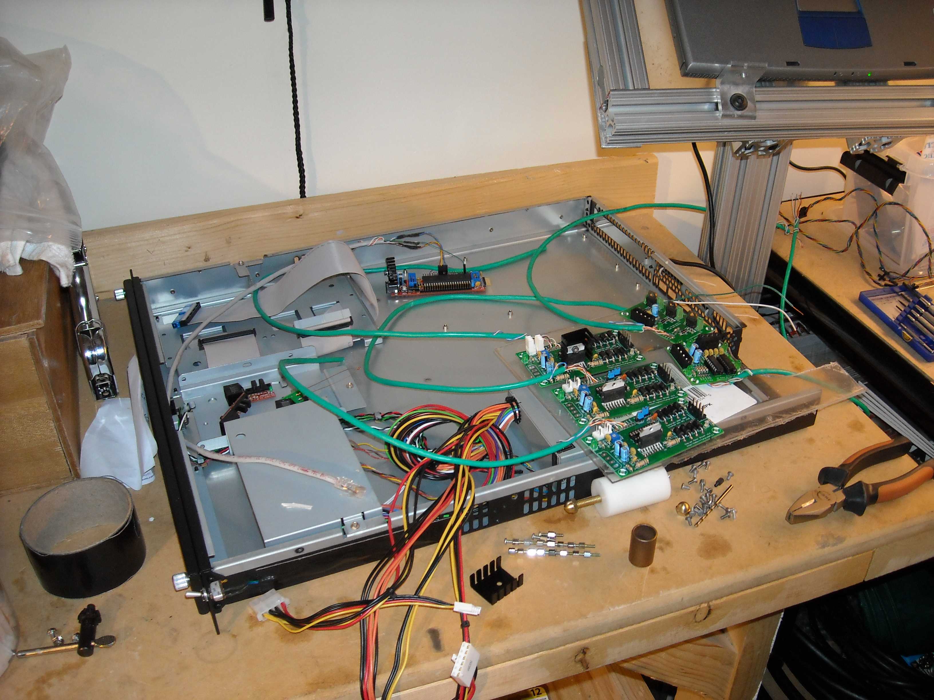
Here's a shot of my setup:
I attached everything to the frame to keep the wire lengths as short as possible.
One thing to watch out for - the motor wires, and to a lesser extent the power wires are very noisy, and the "Step" input to the stepper drivers is very sensitive to noise. I had a stepper driver power wire running alongside one of the step wires for about 6 inches, and that caused my X axis to step whenever the Y was stepping. So, try and separate the input wires from the noisy wires in your enclosure - run them out opposite sides of the enclosure, or at least in separate, shielded and grounded conduits.
Of course, try it out first and see. It'll probably work just fine as is!
Wade
edit:
Although I haven't changed a thing on my driver boards, I very often have to re-wire the Arduino connections as I mess with things, and I'm constantly poking around with scopes and multimeters to see what's going on as I tweak software. In that shot you can see a cheap digital scope and an old analog scope hooked up to the extruder inputs and outputs, and there's a multimeter just out of the shot that I use to monitor the extruder thermocouple as a sanity check. You'll probably want to have a quick release lid on your enclosure for testing, at least until things are running smoothly.
Edited 1 time(s). Last edit at 12/29/2008 02:58PM by Wade Bortz.
Any sort of air flow through your case should keep things cooler than what I've got.
Here's a shot of my setup:

I attached everything to the frame to keep the wire lengths as short as possible.
One thing to watch out for - the motor wires, and to a lesser extent the power wires are very noisy, and the "Step" input to the stepper drivers is very sensitive to noise. I had a stepper driver power wire running alongside one of the step wires for about 6 inches, and that caused my X axis to step whenever the Y was stepping. So, try and separate the input wires from the noisy wires in your enclosure - run them out opposite sides of the enclosure, or at least in separate, shielded and grounded conduits.
Of course, try it out first and see. It'll probably work just fine as is!
Wade
edit:
Although I haven't changed a thing on my driver boards, I very often have to re-wire the Arduino connections as I mess with things, and I'm constantly poking around with scopes and multimeters to see what's going on as I tweak software. In that shot you can see a cheap digital scope and an old analog scope hooked up to the extruder inputs and outputs, and there's a multimeter just out of the shot that I use to monitor the extruder thermocouple as a sanity check. You'll probably want to have a quick release lid on your enclosure for testing, at least until things are running smoothly.
Edited 1 time(s). Last edit at 12/29/2008 02:58PM by Wade Bortz.
|
Re: 25% done December 29, 2008 11:55PM |
Registered: 16 years ago Posts: 82 |
Re: Backlash
Might I suggest, if you are worrying about backlash, an anti-backlash nut? It's basically two nuts with a spring between them so that they are pushed up against the thread, significantly reducing backlash. You use them instead of normal nuts when attaching your carriage to the lead screw. Mind you, it increases friction some, thus reducing the efficiency of your device. This method of reducing backlash is called preload. A much more expensive alternative would be to use a ballscrew. They are much more precise, and have much higher efficiencies (around 90%) but they are often quite short and very expensive.
Regarding the double motor setup, I don't think it was used to solve backlash, as backlash exists between the screw and the nut like you described with your gear illustration. I think that they're actually supposed to solve the inertia problem - where your motor can't stop quickly and you need to change directions. A big problem if you use heavy, fast motors. But not much of a problem on the low-speed reprap.
-Samuel
|
Re: 25% done January 02, 2009 05:09PM |
Registered: 15 years ago Posts: 37 |
Samuel I believe you are correct about the double motors fixing inertia. That was their special thing was that their gantry CNC would accelerate and decelerate all over the place and the huge head definitley had inertia. 2 inch diameter end mill on a tilting head flying around was pretty entertaining to watch! I do believe the double motors also fixed backlash but inertia was the main reason...
So I am going to try out the electronics enclosure and a timing belt for the three axes. How are those bead chains working? I will probably need something stronger as I hope to be able to do some machining with my repstrap.
So I am going to try out the electronics enclosure and a timing belt for the three axes. How are those bead chains working? I will probably need something stronger as I hope to be able to do some machining with my repstrap.
|
Re: 25% done February 09, 2009 02:53PM |
Registered: 15 years ago Posts: 37 |
Been an while since posting as I have been spending my free time mostly on doing some home re-wiring...
Anyone tried using bicycle chain instead of the belt? I would keep a good tension on it but of course the accuracy is suspect. I would have to use some larger sprockets like the front crank granny gear size. I am still un-decided about a belt or low pitch lead screw.
Anyone tried using bicycle chain instead of the belt? I would keep a good tension on it but of course the accuracy is suspect. I would have to use some larger sprockets like the front crank granny gear size. I am still un-decided about a belt or low pitch lead screw.
|
Re: 25% done February 09, 2009 05:36PM |
Registered: 17 years ago Posts: 550 |
HI Mike,
yes the bikechain has been tried (successfully iirc)
You ought to search the forum and the blog to take a look, because I cannot remember exactly I just have that picture in my head of that metal cube with bike chain; sorry.
But it was small sprokets (wheel side; sports gear )
)
Belt if you want to be fast, small pitched lead screw will slow your machine down quite a lot.
(just realize that the machine moves around 5cm/rev with a small belt and only 1mm/rev with some low pitched lead screw)
'sid
yes the bikechain has been tried (successfully iirc)
You ought to search the forum and the blog to take a look, because I cannot remember exactly I just have that picture in my head of that metal cube with bike chain; sorry.
But it was small sprokets (wheel side; sports gear
)Belt if you want to be fast, small pitched lead screw will slow your machine down quite a lot.
(just realize that the machine moves around 5cm/rev with a small belt and only 1mm/rev with some low pitched lead screw)
'sid
|
Re: 25% done February 09, 2009 06:22PM |
Registered: 15 years ago Posts: 332 |
Hi, I successfully tried bikechain: [picasaweb.google.com]#
I used jockey wheels, they're the smallest sprocket I could find, and with the chain the total cost for all axes was ~£20. I get sub-mm precision, not limited by the chain at all. If you want more info, just ask, I can dig up a link to some really nice cheap shimano sprockets if you want.
I used jockey wheels, they're the smallest sprocket I could find, and with the chain the total cost for all axes was ~£20. I get sub-mm precision, not limited by the chain at all. If you want more info, just ask, I can dig up a link to some really nice cheap shimano sprockets if you want.
|
Re: 25% done February 24, 2009 03:44PM |
Registered: 15 years ago Posts: 37 |
Ohh thanks for the response Sid and James I was just talking with one of my roommates about this last night. He works at a bike shop so I may get some used ones cheap... I don't see much for tensioning?? I assumed I would need to pull them tight but maybe not.
I think its time to clean off the work bench and get back into it.
I was just talking with one of my roommates about this last night. He works at a bike shop so I may get some used ones cheap... I don't see much for tensioning?? I assumed I would need to pull them tight but maybe not.I think its time to clean off the work bench and get back into it.
Sorry, only registered users may post in this forum.