Home
>
Reprappers
>
Topic
Ramps 1.4 stepper testing
Posted by dabularach
|
Ramps 1.4 stepper testing May 15, 2014 12:07PM |
Registered: 9 years ago Posts: 14 |
Hello all I built a 3d printer and I going to control it with an arduino mega and ramps 1.4. I tried to connect one of the motors and one driver to test it but I can't get the motor to move. Using an led on the stepper wires I verified what wires go to each coil so the wiring is right. I have a 12 v 20 a power supply connected. I uploaded marlin without issues. My first question is can I make the motor work without connecting everything? I didn't know if the end switch wires, the thermistor wires or anything else has to be hooked up in order for the board to work. The other thing is when I plug the ramps board in the light flashes green for a few seconds and then turns off but the videos I have seen show 2 orange lights flashing constantly on the ramps.
|
Re: Ramps 1.4 stepper testing May 15, 2014 12:48PM |
Registered: 9 years ago Posts: 24 |
I think you also need the relevant end stop micro switch plugged in to the correct place on the RAMPS board to make the circuit for the motor, I believe it will not run if it thinks the micro switch has been activated (i.e. activated means open circuit, which is the same as not being connected).
|
Re: Ramps 1.4 stepper testing May 15, 2014 03:45PM |
Registered: 11 years ago Posts: 99 |
Only the hotend thermistor needs to be plugged in for the board to run (otherwise it mintemps), the green light flashes only for a moment, the orange lights indicate power for D9-D11 and if you invert the endstop logic in the firmware (or connect the GND and signal pins with a jumper) it will circumvent what vince was talking about.
DIY Tech Shop
Through self sustaining actions comes freedom
DIY Tech Shop
|
Re: Ramps 1.4 stepper testing May 15, 2014 04:12PM |
Registered: 9 years ago Posts: 14 |
|
Re: Ramps 1.4 stepper testing May 15, 2014 06:22PM |
Registered: 10 years ago Posts: 474 |
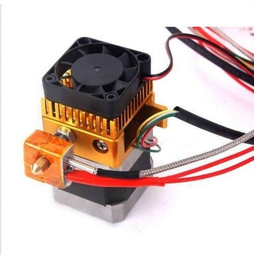
That's a strange looking set up probably Chinese where did you buy it might not even have a thermistor and might have a thermocouple is there any information with it if it has a thermocouple you going to have to modify it to have 100 K thermistor
Edited 1 time(s). Last edit at 05/15/2014 06:23PM by cnc dick.
Edited 1 time(s). Last edit at 05/15/2014 06:23PM by cnc dick.
|
Re: Ramps 1.4 stepper testing May 15, 2014 06:47PM |
Registered: 9 years ago Posts: 12 |
|
Re: Ramps 1.4 stepper testing May 15, 2014 09:23PM |
Registered: 9 years ago Posts: 14 |
|
Re: Ramps 1.4 stepper testing May 15, 2014 09:26PM |
Registered: 9 years ago Posts: 14 |
Here is a link to the eBay page. But they have both thermistors and thermocouple so I'm not sure which one I have.
[m.ebay.com]
[m.ebay.com]
|
Re: Ramps 1.4 stepper testing May 16, 2014 05:36PM |
Registered: 9 years ago Posts: 14 |
|
Re: Ramps 1.4 stepper testing May 16, 2014 08:23PM |
Registered: 10 years ago Posts: 903 |
The metal braided wire is usually a sign of a thermocouple and not a thermistor.
The RAMPS board uses thermistor inputs, because thermistors are cheaper and more common in RepRap projects. A K-type thermocouple can have higher temperature ranges, and is arguably more accurate...and more expensive. I believe that there is an add-on board for RAMPS that will take thermocouple inputs, and has one of the two thermocouple adapter chips (AD-595 being one of them). In the long run, you might be better off just removing the thermocouple and gluing a traditional (and known!) thermistor into the hole.....
The RAMPS board uses thermistor inputs, because thermistors are cheaper and more common in RepRap projects. A K-type thermocouple can have higher temperature ranges, and is arguably more accurate...and more expensive. I believe that there is an add-on board for RAMPS that will take thermocouple inputs, and has one of the two thermocouple adapter chips (AD-595 being one of them). In the long run, you might be better off just removing the thermocouple and gluing a traditional (and known!) thermistor into the hole.....
Sorry, only registered users may post in this forum.