want to ask how to wiring inductive proximity sensor to ramps 1.4 board?
Posted by wendychai80
|
Re: want to ask how to wiring inductive proximity sensor to ramps 1.4 board? April 14, 2015 09:19AM |
Registered: 9 years ago Posts: 51 |
|
Re: want to ask how to wiring inductive proximity sensor to ramps 1.4 board? April 14, 2015 09:32AM |
Registered: 10 years ago Posts: 82 |
|
Re: want to ask how to wiring inductive proximity sensor to ramps 1.4 board? April 14, 2015 09:57AM |
Registered: 9 years ago Posts: 51 |
|
Re: want to ask how to wiring inductive proximity sensor to ramps 1.4 board? April 14, 2015 10:42AM |
Registered: 10 years ago Posts: 82 |
Do you use resistor like in the video?
this is how i wired mine from the sensor into the ramps
from the pictures below,
inside the red circle there got brown and blue near the 11A there where i connect my + and - sensor wire
and another red circle there small black circle inside, there is where i insert my signal wire from the sensor
[imgur.com]
|
Re: want to ask how to wiring inductive proximity sensor to ramps 1.4 board? April 14, 2015 10:50AM |
Registered: 9 years ago Posts: 51 |
Nope.
You connected to the 12-35 input, I connected to the 12-35 output, maybe this is another mistake of mine. But the sensor lights up anyway.
The black cable is in the same position.
I use the same sensor, and did the same resistor hooking. By the way, the only difference is that my resistors instead of 10k and 15k are 100k and 150k.
thanks.
|
Re: want to ask how to wiring inductive proximity sensor to ramps 1.4 board? April 14, 2015 11:00AM |
Registered: 10 years ago Posts: 82 |
|
Re: want to ask how to wiring inductive proximity sensor to ramps 1.4 board? April 14, 2015 11:03AM |
Registered: 9 years ago Posts: 51 |
|
Re: want to ask how to wiring inductive proximity sensor to ramps 1.4 board? April 14, 2015 11:23AM |
Registered: 10 years ago Posts: 82 |
ok. and here what my marlin mechanical settings look like
Edited 1 time(s). Last edit at 04/14/2015 11:24AM by wendychai80.
Quote
//===========================================================================
//=============================Mechanical Settings===========================
//===========================================================================
// Uncomment the following line to enable CoreXY kinematics
// #define COREXY
// coarse Endstop Settings
#define ENDSTOPPULLUPS // Comment this out (using // at the start of the line) to disable the endstop pullup resistors
#ifndef ENDSTOPPULLUPS
// fine endstop settings: Individual pullups. will be ignored if ENDSTOPPULLUPS is defined
// #define ENDSTOPPULLUP_XMAX
// #define ENDSTOPPULLUP_YMAX
// #define ENDSTOPPULLUP_ZMAX
// #define ENDSTOPPULLUP_XMIN
// #define ENDSTOPPULLUP_YMIN
// #define ENDSTOPPULLUP_ZMIN
#endif
#ifdef ENDSTOPPULLUPS
#define ENDSTOPPULLUP_XMAX
#define ENDSTOPPULLUP_YMAX
#define ENDSTOPPULLUP_ZMAX
#define ENDSTOPPULLUP_XMIN
#define ENDSTOPPULLUP_YMIN
// #define ENDSTOPPULLUP_ZMIN
#endif
// The pullups are needed if you directly connect a mechanical endswitch between the signal and ground pins.
const bool X_MIN_ENDSTOP_INVERTING = true; // set to true to invert the logic of the endstop.
const bool Y_MIN_ENDSTOP_INVERTING = true; // set to true to invert the logic of the endstop.
const bool Z_MIN_ENDSTOP_INVERTING = true; // set to true to invert the logic of the endstop.
const bool X_MAX_ENDSTOP_INVERTING = true; // set to true to invert the logic of the endstop.
const bool Y_MAX_ENDSTOP_INVERTING = true; // set to true to invert the logic of the endstop.
const bool Z_MAX_ENDSTOP_INVERTING = true; // set to true to invert the logic of the endstop.
//#define DISABLE_MAX_ENDSTOPS
//#define DISABLE_MIN_ENDSTOPS
// Disable max endstops for compatibility with endstop checking routine
#if defined(COREXY) && !defined(DISABLE_MAX_ENDSTOPS)
#define DISABLE_MAX_ENDSTOPS
#endif
// For Inverting Stepper Enable Pins (Active Low) use 0, Non Inverting (Active High) use 1
#define X_ENABLE_ON 0
#define Y_ENABLE_ON 0
#define Z_ENABLE_ON 0
#define E_ENABLE_ON 0 // For all extruders
// Disables axis when it's not being used.
#define DISABLE_X false
#define DISABLE_Y false
#define DISABLE_Z false
#define DISABLE_E false // For all extruders
#define DISABLE_INACTIVE_EXTRUDER true //disable only inactive extruders and keep active extruder enabled
#define INVERT_X_DIR true // for Mendel set to false, for Orca set to true
#define INVERT_Y_DIR true // for Mendel set to true, for Orca set to false
#define INVERT_Z_DIR false // for Mendel set to false, for Orca set to true
#define INVERT_E0_DIR true // for direct drive extruder v9 set to true, for geared extruder set to false
#define INVERT_E1_DIR false // for direct drive extruder v9 set to true, for geared extruder set to false
#define INVERT_E2_DIR false // for direct drive extruder v9 set to true, for geared extruder set to false
// ENDSTOP SETTINGS:
// Sets direction of endstops when homing; 1=MAX, -1=MIN
#define X_HOME_DIR -1
#define Y_HOME_DIR -1
#define Z_HOME_DIR -1
#define min_software_endstops false // If true, axis won't move to coordinates less than HOME_POS.
#define max_software_endstops true // If true, axis won't move to coordinates greater than the defined lengths below.
// Travel limits after homing
#define X_MAX_POS 210
#define X_MIN_POS 0
#define Y_MAX_POS 210
#define Y_MIN_POS 0
#define Z_MAX_POS 180
#define Z_MIN_POS 0
#define X_MAX_LENGTH (X_MAX_POS - X_MIN_POS)
#define Y_MAX_LENGTH (Y_MAX_POS - Y_MIN_POS)
#define Z_MAX_LENGTH (Z_MAX_POS - Z_MIN_POS)
Edited 1 time(s). Last edit at 04/14/2015 11:24AM by wendychai80.
|
Re: want to ask how to wiring inductive proximity sensor to ramps 1.4 board? April 14, 2015 12:27PM |
Registered: 9 years ago Posts: 51 |

|
Re: want to ask how to wiring inductive proximity sensor to ramps 1.4 board? April 14, 2015 01:19PM |
Registered: 10 years ago Posts: 82 |
|
Re: want to ask how to wiring inductive proximity sensor to ramps 1.4 board? April 14, 2015 01:28PM |
Registered: 9 years ago Posts: 51 |
|
Re: want to ask how to wiring inductive proximity sensor to ramps 1.4 board? April 14, 2015 01:43PM |
Registered: 10 years ago Posts: 82 |
|
Re: want to ask how to wiring inductive proximity sensor to ramps 1.4 board? April 14, 2015 02:02PM |
Registered: 9 years ago Posts: 51 |
|
Re: want to ask how to wiring inductive proximity sensor to ramps 1.4 board? April 14, 2015 02:07PM |
Registered: 10 years ago Posts: 82 |
 wish you luck to solve the problem
|
Re: want to ask how to wiring inductive proximity sensor to ramps 1.4 board? April 15, 2015 07:39AM |
Registered: 9 years ago Posts: 51 |
|
Re: want to ask how to wiring inductive proximity sensor to ramps 1.4 board? April 15, 2015 09:45AM |
Registered: 10 years ago Posts: 82 |
Glad to hear it working for you
for me i do it like this
1: use a4 paper to position the nozzle properly
2: fix the sensor position
3: home all axis using G28 command
4: send G29 to probe bed
5: after it finish the G29 command then send this command G92Z10 this is to make the nozzle think it 10mm away from the bed
6: use A4 paper again and lower z axis 0.1 until you can feel the nozzle slightly touch the paper.
7: After that send M114 command to check all the axis position you will get something like this "X:0.00 Y:0.00 Z:0.00 E:250.00 Count X: 0.00 Y:0.00 Z:0.00"
8: Then just minus the current Z axis position with 10 (examples Z:9.80 so you should minus 9.80-10 = -0.2)
9: Inside your configuration.h find #define Z_PROBE_OFFSET_FROM_EXTRUDER 0.0 and change 0.0 to whatever result you get just now
10: then upload it to you controller
Hope this works for you.
|
Re: want to ask how to wiring inductive proximity sensor to ramps 1.4 board? April 18, 2015 01:03PM |
Registered: 10 years ago Posts: 55 |
I am having some problems hooking this up also. I have a NPN capacitive proximity sensor, hooked up with the 12V. If I just test it by itself, it seems to work fine. The red LED on the back lights up when it gets close to object, and the sensor wire (Black) goes from 9.5V to 0. The problem is in order to hook up to RAMPS I got a LM7805, and when i connect it to the sensor, the LED comes hard on, and I do not get any input as if was being triggered. Any ideas?
Thanks.
Thanks.
|
Re: want to ask how to wiring inductive proximity sensor to ramps 1.4 board? April 20, 2015 09:16AM |
Registered: 10 years ago Posts: 55 |
Quote
CptanPanic
I am having some problems hooking this up also. I have a NPN capacitive proximity sensor, hooked up with the 12V. If I just test it by itself, it seems to work fine. The red LED on the back lights up when it gets close to object, and the sensor wire (Black) goes from 9.5V to 0. The problem is in order to hook up to RAMPS I got a LM7805, and when i connect it to the sensor, the LED comes hard on, and I do not get any input as if was being triggered. Any ideas?
Thanks.
So I did some more research, and it seems that I had things wrong. As this is a NPN sensor it seems I do not need the LM7805, as it acts as an open collector. So I should be able to just connect to endstop sensor pin with internal pullup, but this doesn't work either. When I do this, the LED on the sensor turns on as soon as I connect to pin.
|
Re: want to ask how to wiring inductive proximity sensor to ramps 1.4 board? April 20, 2015 09:21AM |
Registered: 9 years ago Posts: 51 |
|
Re: want to ask how to wiring inductive proximity sensor to ramps 1.4 board? April 20, 2015 09:31AM |
Registered: 10 years ago Posts: 82 |
Quote
CptanPanic
Quote
CptanPanic
I am having some problems hooking this up also. I have a NPN capacitive proximity sensor, hooked up with the 12V. If I just test it by itself, it seems to work fine. The red LED on the back lights up when it gets close to object, and the sensor wire (Black) goes from 9.5V to 0. The problem is in order to hook up to RAMPS I got a LM7805, and when i connect it to the sensor, the LED comes hard on, and I do not get any input as if was being triggered. Any ideas?
Thanks.
So I did some more research, and it seems that I had things wrong. As this is a NPN sensor it seems I do not need the LM7805, as it acts as an open collector. So I should be able to just connect to endstop sensor pin with internal pullup, but this doesn't work either. When I do this, the LED on the sensor turns on as soon as I connect to pin.
Sorry CptanPanic i didnt familiar with other sensor cause im just following other guide that i found and ask question here and there regarding my problem.
the sensor red led shine bright or just dim? or maybe you should double check your wiring again cause gustavogoulart sensor didnt work also until he fix the resistor wiring. Everything about wiring the sensor should be in this thread, and if this doesnt help you maybe you should open new thread about your problem cause i lack of knowledge about electronic thing.
|
Re: want to ask how to wiring inductive proximity sensor to ramps 1.4 board? April 20, 2015 09:34AM |
Registered: 10 years ago Posts: 82 |
Quote
gustavogoulart
Hello! Everything working here, the problem (aside the error I made with the wires) was the firmware. I was using one branch, and the branch has some bug that causes this problem. Solved now here with the stable firmware.
Branch? is it in marlin firmware? lol i didnt know what that is. nevermind then, nice to hear everything work fine for you now

|
Re: want to ask how to wiring inductive proximity sensor to ramps 1.4 board? April 21, 2015 07:20AM |
Registered: 10 years ago Posts: 55 |
Quote
wendychai80
Quote
CptanPanic
Quote
CptanPanic
I am having some problems hooking this up also. I have a NPN capacitive proximity sensor, hooked up with the 12V. If I just test it by itself, it seems to work fine. The red LED on the back lights up when it gets close to object, and the sensor wire (Black) goes from 9.5V to 0. The problem is in order to hook up to RAMPS I got a LM7805, and when i connect it to the sensor, the LED comes hard on, and I do not get any input as if was being triggered. Any ideas?
Thanks.
So I did some more research, and it seems that I had things wrong. As this is a NPN sensor it seems I do not need the LM7805, as it acts as an open collector. So I should be able to just connect to endstop sensor pin with internal pullup, but this doesn't work either. When I do this, the LED on the sensor turns on as soon as I connect to pin.
Sorry CptanPanic i didnt familiar with other sensor cause im just following other guide that i found and ask question here and there regarding my problem.
the sensor red led shine bright or just dim? or maybe you should double check your wiring again cause gustavogoulart sensor didnt work also until he fix the resistor wiring. Everything about wiring the sensor should be in this thread, and if this doesnt help you maybe you should open new thread about your problem cause i lack of knowledge about electronic thing.
So it turns out it is actually working correct although the LED on the sensor is always lit.
|
Re: want to ask how to wiring inductive proximity sensor to ramps 1.4 board? April 24, 2015 09:04PM |
Registered: 9 years ago Posts: 1 |
Hi
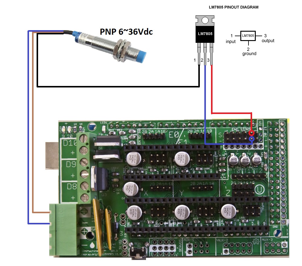
Sorry to jump in on an open thread but can you please just confirm that with a 12 volt PNP type proximity you require two bridging resistors 10k and 15k por use the LM7805 diagram and if you use an 12 volt NPN type proximity you just require the pull down resistor to be enabled in the software?
Lastly capacitive sensors in my experience are very inaccurate and large. Why wouldn't you just take off the glass and install an aluminium plate with an inductive sensor?
|
Re: want to ask how to wiring inductive proximity sensor to ramps 1.4 board? July 06, 2015 06:35AM |
Registered: 9 years ago Posts: 51 |
Hi there!
I bought the regulator, but I´m afraid I can fry everything because I have no practice in eletronics, can someone show a diagram on how to wire things like this quote?
thanks,
I bought the regulator, but I´m afraid I can fry everything because I have no practice in eletronics, can someone show a diagram on how to wire things like this quote?
thanks,
Quote
ggherbaz
I usually set my sensors this way:
Brown and blue goes to power supply, this way I know my sensor have enough power to give me maximum sensing distance. Then I connect the black signal wire to an LM7805 pin 1, pin 2 goes to ground and pin 3 (regulated 5 volts) goes to signal pin on endstop connector.
There is a risk that if the regulator fails, the whole 12 volts will go to the board frying it, but it is minimal since usually when the regulator fails they stop supplying voltage and also the power consumption it so small that the regulator never get stressed enough to make it fail.
|
Re: want to ask how to wiring inductive proximity sensor to ramps 1.4 board? July 06, 2015 06:45AM |
Registered: 10 years ago Posts: 82 |
|
Re: want to ask how to wiring inductive proximity sensor to ramps 1.4 board? July 10, 2015 09:33PM |
Registered: 8 years ago Posts: 80 |
jad51
I can confirm that the pnp will work with the resistor set up. the 10k resistor acts as a pull down also. Made up one but didn't connect to signal on board. It has no voltage when it is not near metal meaning no but voltage goes to 12 volts ( no load on 15k) when near metal (nc). Wise to use the 5 volt regulator. Firmware needs to be change in the logic settings.
I can confirm that the pnp will work with the resistor set up. the 10k resistor acts as a pull down also. Made up one but didn't connect to signal on board. It has no voltage when it is not near metal meaning no but voltage goes to 12 volts ( no load on 15k) when near metal (nc). Wise to use the 5 volt regulator. Firmware needs to be change in the logic settings.
|
Re: want to ask how to wiring inductive proximity sensor to ramps 1.4 board? September 02, 2015 02:03PM |
Registered: 8 years ago Posts: 2 |
Hi! I'm currently following this thread and I am very excited to try this out on my Graber i3...So after reading all the posts in this thread, I want to ask if this setup on attached image is the one correct to use the PNP proximity sensor with a LM7805 regulator. Do I need connect the LM7805 pin 2 (ground) as in the image or in same ground connection of PNP sensor?
Thank you all for all informations so far!
Thank you all for all informations so far!
|
Re: want to ask how to wiring inductive proximity sensor to ramps 1.4 board? September 11, 2015 11:17PM |
Registered: 10 years ago Posts: 814 |
I have a M12 NPN 3 wire NO proximity sensor.
Wiring it the way Smerrett79 did on his Smartrap Core..
Brown - 12v
Black - Ground
Blue - Signal
I get a Dimly lit LED and 2.84v without metal near sensor, and a Brightly lit LED and 0v with metal near sensor.
I connected the blue directly to RAMPS Zmin Signal as he said to, and it worked.
I made sure ZMin Endstop Inverting was set as true like below.
const bool Z_MIN_ENDSTOP_INVERTING = true;
Borrowed the Image above and edited it to match for NPN sensors.
Edited 1 time(s). Last edit at 09/11/2015 11:18PM by madmike8.
Wiring it the way Smerrett79 did on his Smartrap Core..
Brown - 12v
Black - Ground
Blue - Signal
I get a Dimly lit LED and 2.84v without metal near sensor, and a Brightly lit LED and 0v with metal near sensor.
I connected the blue directly to RAMPS Zmin Signal as he said to, and it worked.
I made sure ZMin Endstop Inverting was set as true like below.
const bool Z_MIN_ENDSTOP_INVERTING = true;
Borrowed the Image above and edited it to match for NPN sensors.

Edited 1 time(s). Last edit at 09/11/2015 11:18PM by madmike8.
|
Re: want to ask how to wiring inductive proximity sensor to ramps 1.4 board? September 12, 2015 12:16PM |
Registered: 8 years ago Posts: 2 |
Quote
madmike8
I have a M12 NPN 3 wire NO proximity sensor.
Wiring it the way Smerrett79 did on his Smartrap Core..
Brown - 12v
Black - Ground
Blue - Signal
I get a Dimly lit LED and 2.84v without metal near sensor, and a Brightly lit LED and 0v with metal near sensor.
I connected the blue directly to RAMPS Zmin Signal as he said to, and it worked.
I made sure ZMin Endstop Inverting was set as true like below.
const bool Z_MIN_ENDSTOP_INVERTING = true;
Borrowed the Image above and edited it to match for NPN sensors.
[attachment 62002 RAMPS_NPNProximitySensor.png]
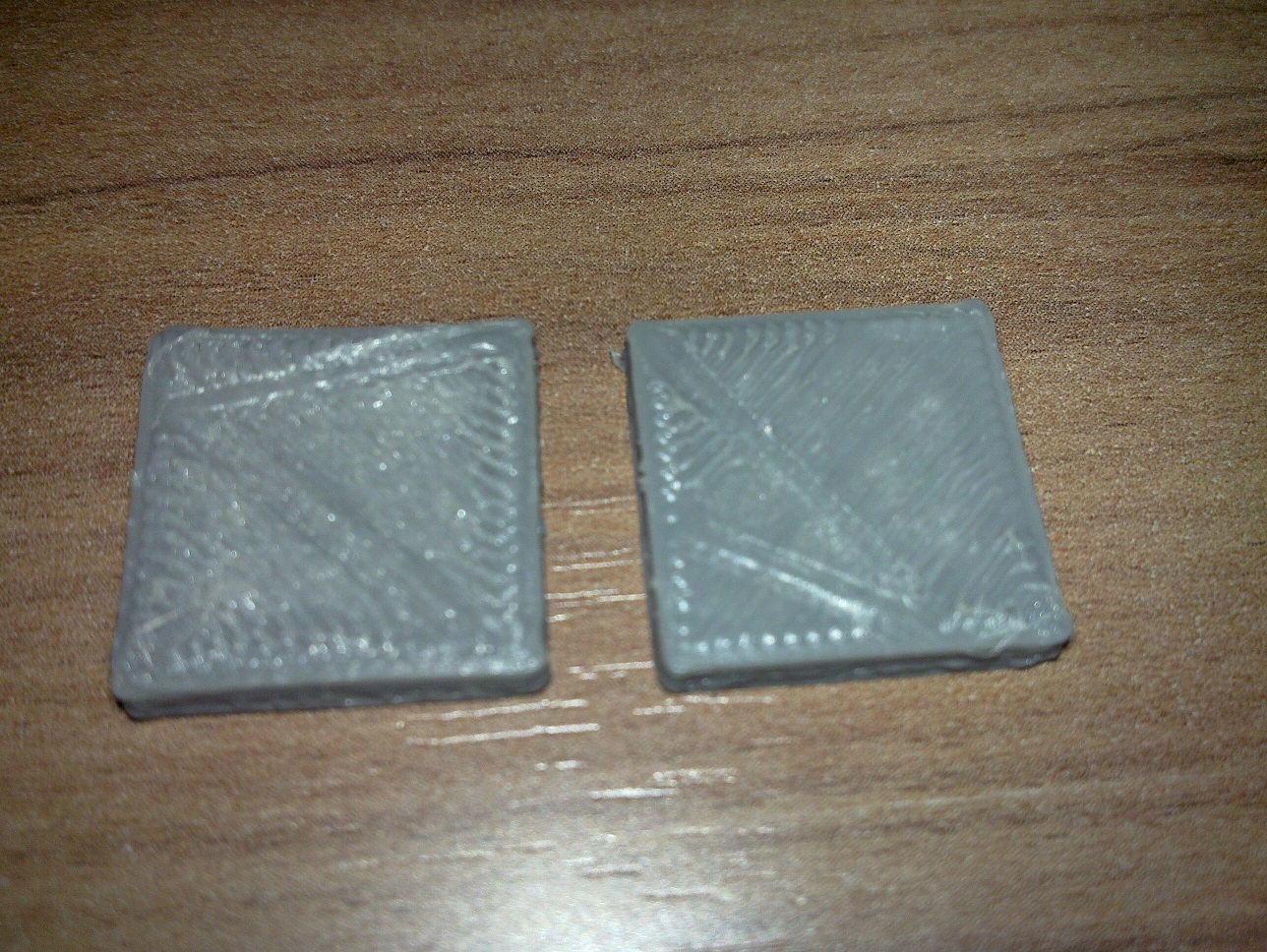
Yes! I used a NPN sensor as well. Worked out pretty well but I had to use a voltage divider. The only problem now is that my layers seems to be "sliced" by the nozzle...the first layers are good but I notice that the top of them (all other layers) had been marked by the nozzle, almost as if the Z axis are not going up as high as it supposed to be...maybe it's the weight added by the sensor? I don't know... :/
EDIT 1: I figured out that the problem is on X and Y axis.... these attached 3d printed parts supposed to be 20mmx20mmx3mm (XxYxZ) but I got 16.7mmx16.7mmx3mm I think I need to tweak the firmware again because I dont think this is related to the belts...
EDIT 2: It was the DEFAULT_AXIS_STEPS_PER_UNIT hehehe

Edited 3 time(s). Last edit at 09/12/2015 03:16PM by mccarmo.

Sorry, only registered users may post in this forum.