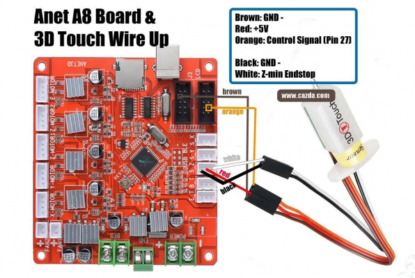
Where is Pin 29 on a ANET3D V1.-5. board (needed for BL-Touch)
Posted by Corpsman
|
Where is Pin 29 on a ANET3D V1.-5. board (needed for BL-Touch) January 12, 2024 12:33AM |
Registered: 3 months ago Posts: 4 |
Hello Community,
I am more a Hobbyist than a pro, but since 5 Years a owner of a Anet E10 printer, and it all worked. During the Christmas season i decided to add a new feature to my printer. The Bed Leveling.
So i first replaced the Firmware with the Marlin 2.? Software. Next i designed and printed all adapters needed to mount the BL-Touch to my printer and mounted it. Then i followed this instructions ( [www.cazda.com] ) which says
After Uploading the new Firmware nothing worked and i started searching the web, why.
I ended up with this video: [www.youtube.com] And at the very end the author said that he needed to change the pin from 27 to 29 in order to get it to work. Then i checked the "pins_ANET_10.h" file, and yes there it stands:
So i think the SW-Part i get managed. But i did not find any information, where that pin 29 is physically on my board and where to solder the control wire of the BL-Touch onto my board. Can anyone of you help me ?
I am more a Hobbyist than a pro, but since 5 Years a owner of a Anet E10 printer, and it all worked. During the Christmas season i decided to add a new feature to my printer. The Bed Leveling.
So i first replaced the Firmware with the Marlin 2.? Software. Next i designed and printed all adapters needed to mount the BL-Touch to my printer and mounted it. Then i followed this instructions ( [www.cazda.com] ) which says
#define SERVO0_PIN 27
After Uploading the new Firmware nothing worked and i started searching the web, why.
I ended up with this video: [www.youtube.com] And at the very end the author said that he needed to change the pin from 27 to 29 in order to get it to work. Then i checked the "pins_ANET_10.h" file, and yes there it stands:
// Line 202
#define SERVO0_PIN 29
So i think the SW-Part i get managed. But i did not find any information, where that pin 29 is physically on my board and where to solder the control wire of the BL-Touch onto my board. Can anyone of you help me ?
|
Re: Where is Pin 29 on a ANET3D V1.-5. board (needed for BL-Touch) January 12, 2024 01:44AM |
Admin Registered: 13 years ago Posts: 7,005 |
from current pins_ANET_10.h (you might have older code, I only added this graphic to bugfix 2 weeks ago)
You can see D29 on the LCD connector
SERVO0_PIN is the BLTOUCH control wire
the bltouch trigger wire goes to your Z-stop pin
The diagram is close enough.. you just need to move the orange cable up two pin on the lcd connector.
NOTE, all these bltouch and clones all have different coloured wiring.
you should not blindly follow the colours
instead find the two gnds (brown and black in this example), from there you can work out the order of the pins.
Edited 7 time(s). Last edit at 01/12/2024 02:14AM by Dust.
/**
 * Connector pinouts
 *
 *            ------                            ------                             ----
 * (SDA) D17 | 1  2 | (A1) D30             3V3 | 1  2 | D4 (SS)             J3_RX |1  2| J3_TX
 * (SCL) D16 | 3  4 | (A2) D29             GND | 3  4 | RESET            (TXO) D9 |3  4| D8 (RX0) D8
 *       D11 | 5  6   (A3) D28      (MOSI) D5  | 5  6   D7 (SCK)           USB_RX |5  6| USB_TX
 *       D10 | 7  8 | (A4) D27             5V  | 7  8 | D6 (MISO)                  ----
 *       5V  | 9 10 | GND                J3_RX | 9 10 | J3_TX
 *            ------                            ------
 *             LCD                                J3                              USB_BLE
 */
You can see D29 on the LCD connector
SERVO0_PIN is the BLTOUCH control wire
the bltouch trigger wire goes to your Z-stop pin
The diagram is close enough.. you just need to move the orange cable up two pin on the lcd connector.
NOTE, all these bltouch and clones all have different coloured wiring.
you should not blindly follow the colours
instead find the two gnds (brown and black in this example), from there you can work out the order of the pins.
Edited 7 time(s). Last edit at 01/12/2024 02:14AM by Dust.
|
Re: Where is Pin 29 on a ANET3D V1.-5. board (needed for BL-Touch) January 12, 2024 02:29AM |
Registered: 3 months ago Posts: 4 |
Wow, thanks that helps a lot, thanks.
Do i get this right, that i can solder the "brown" cable (which stands for Ground") also to the connector where the orange cable is soldered ? This would reduce the number of needed connectors, resulting in this wiring.
Do i get this right, that i can solder the "brown" cable (which stands for Ground") also to the connector where the orange cable is soldered ? This would reduce the number of needed connectors, resulting in this wiring.
 ------
| 1  2 |
| 3  4 | Orange
| 5  6
| 7  8 |
| 9 10 | Brown
 ------
|
Re: Where is Pin 29 on a ANET3D V1.-5. board (needed for BL-Touch) January 12, 2024 02:31AM |
Admin Registered: 13 years ago Posts: 7,005 |
|
Re: Where is Pin 29 on a ANET3D V1.-5. board (needed for BL-Touch) January 12, 2024 02:35AM |
Registered: 3 months ago Posts: 4 |
|
Re: Where is Pin 29 on a ANET3D V1.-5. board (needed for BL-Touch) January 16, 2024 03:54AM |
Registered: 3 months ago Posts: 4 |
Sorry, only registered users may post in this forum.

