Strange stepper behaviour
Posted by Viking68
|
Strange stepper behaviour January 02, 2020 08:17PM |
Registered: 4 years ago Posts: 4 |
Hello All,
I have a Geetech delta printer and I just installed Marlin 2.0.x
I have 200 step/rev step-motors with A4988 stepper modules.
When I ask the printer to move in the Z direction in steps of 0.01 mm, something only happens on the motor every 0.075mm.
Any Idea why that could be ? Stepper controllers are set to use 16 microsteps so with:
#define XYZ_FULL_STEPS_PER_ROTATION 200
#define XYZ_MICROSTEPS 16
#define XYZ_BELT_PITCH 2
#define XYZ_PULLEY_TEETH 20
#define DEFAULT_XYZ_STEPS_PER_UNIT 80
The printer should be able to move 0.0125 mm on each microstep.
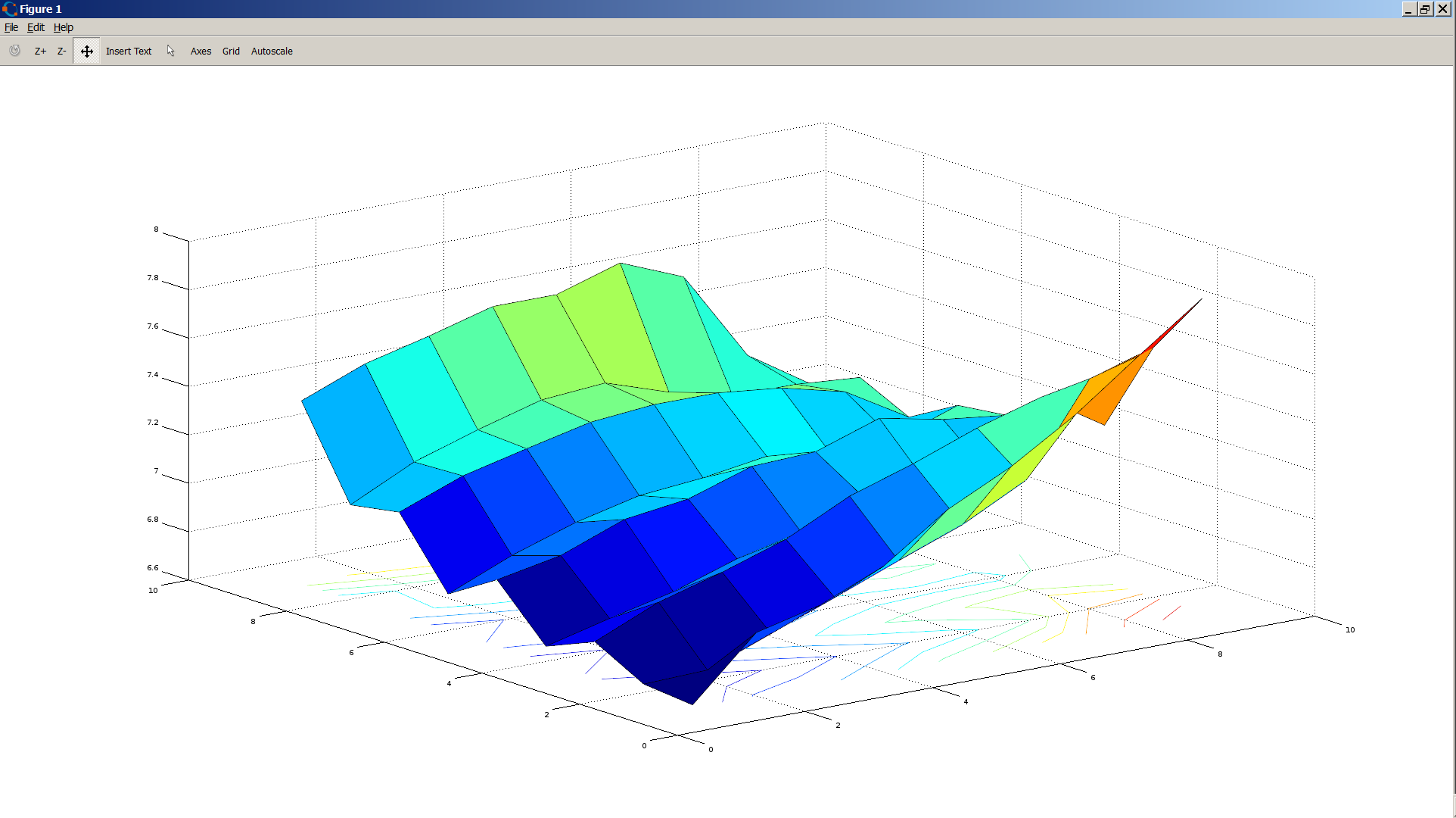
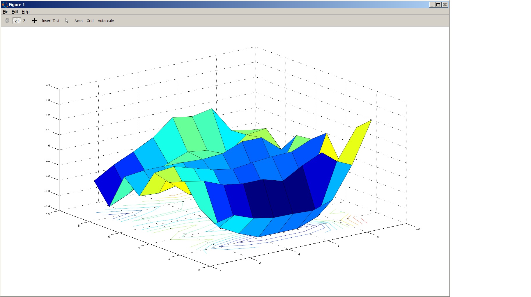
This issue also causes auto-leveling to have a big and periodic error. See attached mesh plot.
I suppose the marlin sw uses high enough precision math in it's calculations..
I have a Geetech delta printer and I just installed Marlin 2.0.x
I have 200 step/rev step-motors with A4988 stepper modules.
When I ask the printer to move in the Z direction in steps of 0.01 mm, something only happens on the motor every 0.075mm.
Any Idea why that could be ? Stepper controllers are set to use 16 microsteps so with:
#define XYZ_FULL_STEPS_PER_ROTATION 200
#define XYZ_MICROSTEPS 16
#define XYZ_BELT_PITCH 2
#define XYZ_PULLEY_TEETH 20
#define DEFAULT_XYZ_STEPS_PER_UNIT 80
The printer should be able to move 0.0125 mm on each microstep.
This issue also causes auto-leveling to have a big and periodic error. See attached mesh plot.
I suppose the marlin sw uses high enough precision math in it's calculations..
|
Re: Strange stepper behaviour January 02, 2020 10:56PM |
Admin Registered: 13 years ago Posts: 7,007 |
Yes this is reality vs computer view.
In reality you cannot move a stepper motor in 1/16th micro stepping, 1/4 is closer to reality on most steppers, the odd stepper can do 1/8 reliably..
Stepping is cumulative in reality, you ask it to move a step, and it can't physically do it, you add more steps and it eventually does move to the correct location. So the result is steps are not lost, but you don't get the theoretical resolution.
This is part of the reason people recommend 0.9 degree steppers on deltas
But if your trying to do something that needs that sort of resolution you need mechanical gearing on the stepper motors
Everyone has this issue, so i don't this is not likely to be the cause of your issue.
|
Re: Strange stepper behaviour January 03, 2020 03:18AM |
Registered: 4 years ago Posts: 4 |
Hey Dust,
Thanks for your input. Yes I'm aware that micro stepping is far from perfect, but this behaviour is like having only half steps. The motor is not moving at all between the steps
The stepper controller doesn't look that bad from the datasheet, but I guess - just for the quriosity of it I will have to test it with another motor and see what it can do.
Somebody have tested that controller (https://hackaday.com/2016/08/29/how-accurate-is-microstepping-really/ ) and found it to pretty good - but I wan't to see it myself.
I guess I could turn on debug output for the coordinate transformation and step control code to see what the SW instruct it to do.
But first I will put a scope on the step pin for the motor to see if it does get a step or if it gets 7/8 steps at a time.
This is a new release fo Marlin, so who knwo what coudl ahve happened along the way..
|
Re: Strange stepper behaviour January 03, 2020 04:12AM |
Admin Registered: 16 years ago Posts: 13,891 |
Quote
Dust
Yes this is reality vs computer view.
In reality you cannot move a stepper motor in 1/16th micro stepping, 1/4 is closer to reality on most steppers, the odd stepper can do 1/8 reliably..
... this is mostly correct in the "3D-printing-world", where small, underpowered NEMA-14 to -17 steppers are used.
With higher powered steppers (NEMA-23 2Nm-types or even bigger, some of them geared) I'm using up to 1/256 microstepping with noticeable differenzes in resolution/accuracy and sound, when switching between 1/64 to 1/128

Viktor
--------
Aufruf zum Projekt "Müll-freie Meere" - [reprap.org] -- Deutsche Facebook-Gruppe - [www.facebook.com]
Call for the project "garbage-free seas" - [reprap.org]
|
Re: Strange stepper behaviour January 03, 2020 06:16PM |
Registered: 4 years ago Posts: 4 |
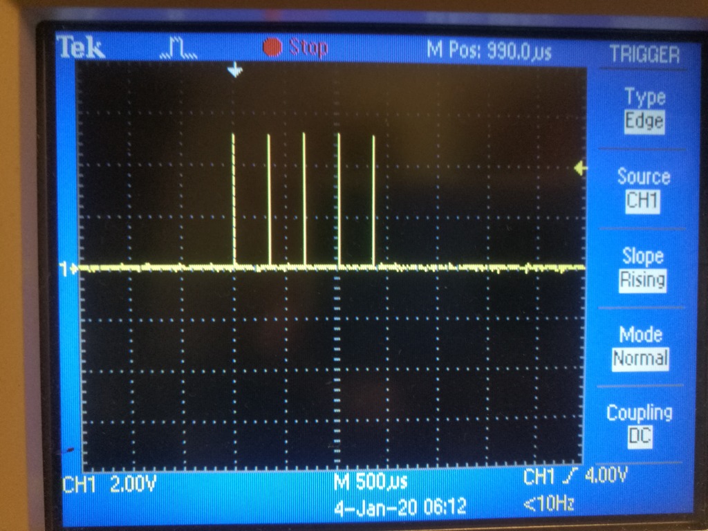
Well after probing the STEP input on the motor controller, it turns out that the SW gives 5 steps at a time.
So much for micro stepping and high resolution !
Now I guess the hunt is to find the reason why SW is doing this - why on earth is it doing it - and can it be changed...
Scope shot enclosed.
So much for micro stepping and high resolution !
Now I guess the hunt is to find the reason why SW is doing this - why on earth is it doing it - and can it be changed...
Scope shot enclosed.
|
Re: Strange stepper behaviour January 03, 2020 06:42PM |
Admin Registered: 16 years ago Posts: 13,891 |
... hmmm ... there is somewhere an option for"babystepping", which outputs 4 pulses per step 
But could be, if you're moving with "smallest step", what is normally 0,1mm -- so depends on your settings, how many pulses this will output ...
Viktor
--------
Aufruf zum Projekt "Müll-freie Meere" - [reprap.org] -- Deutsche Facebook-Gruppe - [www.facebook.com]
Call for the project "garbage-free seas" - [reprap.org]
|
Re: Strange stepper behaviour January 05, 2020 11:31AM |
Registered: 4 years ago Posts: 4 |
In config_adv.h for Marlin, there is the following define:
#define MIN_STEPS_PER_SEGMENT 6
This seems to determine the limit of how many steps should minimally be executed. Default is 6, so that means 5 or more pulses are issued at a time. Why it's the value minus I don't know. I've set it to 1.
After changeing it, the motor moves as it should, although some step phases are difficult for the motor to be in and results in almost no movement (btw does anyone know what the potentiometer on the step A4988 board is used for ?).
The surface levelling still contains a periodic error, specially in one direction - so I've changed the config from AUTO_BED_LEVELING_BILINEAR to AUTO_BED_LEVELING_LINEAR as bilinear does not have a chance to work properly when the mesh points go up and down like that. Instead I guess the AUTO_BED_LEVELING_LINEAR option does an average and calculates the best fitting plane. This of course assumes the print plate is flat which is not always the case. Mine was aluminium but I've since added a spring steel plate so it's probably much more flat then before (though I think it's below 0.1 mm) - it's a 210 mm diameter plate.
But as "Dust" mentioned before, a 400 steps/rev stepper is a better choise for deltas to increase precision and a physically bigger stepper with a higher drive current, I would think would also improve the precision of microstepping.
Anyone knows why the surface level scan is only rectangular - even on a delta ? It should be a circular scan. I know it would probably require a lookup table to find the surrounding grid points in bilinear interpolation mode, but it would allow scanning the whole print surface instead of just a smaller rectangle..
Besides that, I'm moving my inductive probe to the center of the extruder hotends to reduce the problem of the tilt of the hotend carriage. Though I've adjusted the home positions to activate at the same distance from the actuators, the hotend carriage does not move in a level way. With the sensor being 30 mm away from the (two) extruders, the tangential relation between the angle and the height really amplifies any change in the tilt of the hotend carriage. Well now I'm stuck, as the thread for the probe is a M12x1mm, which is not a common size - and there is no room for a nut - I guess I'll have to use teflon to be able to tighten it to a certain position (height).
So much fun with a cheap Chinese delta printer - but I guess you learn a thing or two (the hard way) ;-)
Sorry, only registered users may post in this forum.