Marlin 2.x on ReARM - filament width sensor question
Posted by AndY_1981
|
Marlin 2.x on ReARM - filament width sensor question March 16, 2020 07:13PM |
Registered: 4 years ago Posts: 12 |
Hello all,
i tried to set up the filament width sensor function to test it before using it with the following setup:
REARM board with Ramps 1.6 addon ... REPRAP_DISCOUNT_FULL_GRAPHIC_SMART_CONTROLLER ... No SDSupport
I have replaced the sensor by a poti. I get a filament width shown on the display but ... I need to have an input voltage of round about 0.5V that the display shows 1.75 mm ... i have used a 25 turn poti and it is more or less impossible to set an exact value because it is so sensitive ... i´m talking about ~0.2V from 2,5mm to 0,5mm.
I hope someone can help me.
BR Andy
|
Re: Marlin 2.x on ReARM - filament width sensor question March 30, 2020 01:04PM |
Registered: 4 years ago Posts: 6 |
|
Re: Marlin 2.x on ReARM - filament width sensor question March 31, 2020 04:37PM |
Registered: 4 years ago Posts: 12 |
Perhaps I have expressed myself wrong.
I tried everything from zero.
I have activated the filament thick measurement as follows in the Configuration_adv.h:
The Pin is defined in pins_RAMPS_RE_ARM.h:
If I understand the function of the filament thickness sensor correctly, a voltage proportional to the filament thickness is applied to the analog input. In a 5V system for example, 1.75mm = 1.75V at the analog input. ... please correct me if I am wrong!
Therefore I have assumed that with my Re-Arm @3.3V and 1.115V on the analog input, 1.75mm filament thickness will be shown in the display.
But exactly here is the problem.
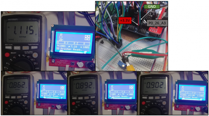
With 1.115V on the analog input i get a filament diameter of 7,22mm on the LCD. Please see the picture below.
I have found out through several tests that the displayed filament thickness is linear to the voltage at the analog input. Per 0.02V change in voltage the displayed filament diameter changes by 0.25mm +- 0.02mm.
For this reason I think it is a problem in the firmware.
And to explain why I installed a potentiometer instead of the actual sensor ...
The actual sensor is not ready yet ...
i want to build a 3D-printer and want to test the electrics before i build the mechanics.
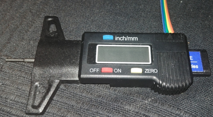
As a filament thick sensor I want to use a digital caliper which I read with an arduino Nano.
The Nano will then output the filament thickness as voltage via DAC. ... So the plan ... But if the input don´t work it makes no sense.
I tried everything from zero.
I have activated the filament thick measurement as follows in the Configuration_adv.h:
#define FILAMENT_WIDTH_SENSOR

#if ENABLED(FILAMENT_WIDTH_SENSOR)
  #define FILAMENT_SENSOR_EXTRUDER_NUM 0    // Index of the extruder that has the filament sensor. :[0,1,2,3,4]
  #define MEASUREMENT_DELAY_CM        14    // (cm) The distance from the filament sensor to the melting chamber

  #define FILWIDTH_ERROR_MARGIN        1.0  // (mm) If a measurement differs too much from nominal width ignore it
  #define MAX_MEASUREMENT_DELAY       20    // (bytes) Buffer size for stored measurements (1 byte per cm). Must be larger than MEASUREMENT_DELAY_CM.

  #define DEFAULT_MEASURED_FILAMENT_DIA DEFAULT_NOMINAL_FILAMENT_DIA // Set measured to nominal initially

  // Display filament width on the LCD status line. Status messages will expire after 5 seconds.
  #define FILAMENT_LCD_DISPLAY
#endif
I have connected a potentiometer to replace the actual sensor for testing. It is connected to +3.3V, P0_26_A3 and GND.
The Pin is defined in pins_RAMPS_RE_ARM.h:
#define FILWIDTH_PIN P0_26_A3 // A3 - (63) - J5-3 & AUX-2I measure the voltage between P0_26_A3 and GND with a multimeter. See picture below.
If I understand the function of the filament thickness sensor correctly, a voltage proportional to the filament thickness is applied to the analog input. In a 5V system for example, 1.75mm = 1.75V at the analog input. ... please correct me if I am wrong!
Therefore I have assumed that with my Re-Arm @3.3V and 1.115V on the analog input, 1.75mm filament thickness will be shown in the display.
But exactly here is the problem.
With 1.115V on the analog input i get a filament diameter of 7,22mm on the LCD. Please see the picture below.
I have found out through several tests that the displayed filament thickness is linear to the voltage at the analog input. Per 0.02V change in voltage the displayed filament diameter changes by 0.25mm +- 0.02mm.
For this reason I think it is a problem in the firmware.
And to explain why I installed a potentiometer instead of the actual sensor ...
The actual sensor is not ready yet ...
i want to build a 3D-printer and want to test the electrics before i build the mechanics.
As a filament thick sensor I want to use a digital caliper which I read with an arduino Nano.
The Nano will then output the filament thickness as voltage via DAC. ... So the plan ... But if the input don´t work it makes no sense.
Sorry, only registered users may post in this forum.

