Thermocouple Sensor v1.0
Contents
Thermocouple Sensor v1.0
I am a part of both the Generation 2 Electronics and Generation 3 Electronics Systems.
Overview
<div class="thumb tright"></div>
This is a simple board for measuring temperature. It uses an AD595 chip to make thermocouple measurements easy. The AD595 amplifies the thermocouple signal and conditions it for easy use. Thermocouples are great due to their linearity over a large range, and their high temperature capability (up to 1300C!)
- You'll need a soldering toolkit to do most of this.
- Read our Electronics Fabrication Guide if you're new.
If you want to make your own thermocouples (a lot cheaper than buying them ready-made) then see this page.
Alternatives
There's an alternative to this design here.
Get It!
Full Kit
Raw Components
Files
You can download the electronics files from Sourceforge.
This file contains the following:
- GERBER files for getting it manufactured
- PDF files of the schematic, copper layers, and silkscreen
- Eagle source files for modification
- 3D rendered image as well as POVRay scene file
- exerciser code to test your board.
Interface
| Pin | Function |
| +5 | This is the pin to supply +5 volts on. |
| S | This is the signal pin. It will output a voltage between 0 and 5 volts that correlates with the temperature. |
| G | This is the ground pin. |
Signal Values
The nice thing about the AD595 is that the signal it generates is linear with temperature. This means that it is really easy to convert from an analog reading to a real temperature. Secondly, the AD595 outputs 10mV/C which is simple to work with. at 1V, the temperature is 100C, at 2V, the temperature is 200C, etc. With a reference voltage of 5V, the sensor can make readings up to 500C.
The way to read the temperature is easy. First you convert an analog reading to voltage, then you multiply by 100 to get the temperature in celsius:
Voltage = analogRead(X) * 5.0 / 1024.0; //Note that 5.0 is the A/D reference voltage. Celsius = Voltage * 100;
Or, to simplify:
Celsius = ( 5.0 * analogRead(X) * 100.0) / 1024.0;
More information in the AD595 datasheet.
Thanks to an article on uC Hobby for info on reading values from a very similar sensor.
Thermocouple
This circuit is designed to use the very common Type K thermocouple. There are many other types of thermocouples, and it may be possible to use them as well. You'll get lots of mileage out of a Type K thermocouple though.
More about thermocouples on Wikipedia.
Alarm LED
This LED lights up if there is no thermocouple connected or some other error (like the thermocouple failing, melting, etc). It's a nice, easy way to help you debug things.
Accuracy
The circuit we have provided is very accurate, and will work well for our uses. We have made a few decisions to make the board simpler/easier to use that may slightly degrade its accuracy. However, its easy to build the board in a more accurate way:
- Use the AD595C (accuracy of +/- 1C) - more expensive than recommended AD595A (accuracy of +/- 3C).
- Solder the thermocouple directly to the board.
- Solder the AD595 directly to the board.
By using a more expensive chip and mounting the components directly to the board itself, you will be able to slightly increase the accuracy.
Build It
Board Bugs
- Oh no!! Silkscreen error. I messed up the +/- signs on the screw terminal for the thermocouple. Just swap them, or write over them with sharpie. Make sure you run the test code to make sure you have your thermocouple inserted correctly.
- Please report any bugs you find to the forums.
Printed Circuit Board
<div class="thumb tright"></div>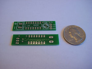
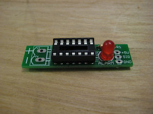
You can either buy this PCB from the RepRap Research Foundation, or you can make your own. The image above shows the professionally manufactured PCB ready for soldering. Its also cheap, only $1.00 USD.
Components
<div class="thumb tright"></div>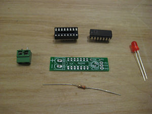
<iframe src="http://parts.reprap.org/embed/module/Thermocouple+Sensor+v1.0" width="600" height="350" frameborder="0">Visit http://parts.reprap.org/embed/module/Thermocouple+Sensor+v1.0</iframe>
Soldering Instructions
<div class="thumb tright"></div>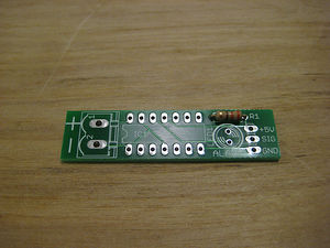
R1
You can insert the resistor in any orientation. Pay attention to the color bands.
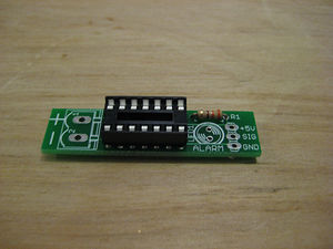
SOCKET
The socket has a notch on one end. Line that up with the semicircle on the silkscreen.
LED1
LEDs have a polarity, and need to be inserted in the proper direction. Your LED should have a flat side. Line that up with the flat side on the silkscreen and solder it in.
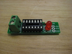
Thermocouple Terminal
Solder the screw terminals with the openings facing the outside.
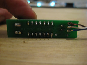
Wires
Trim 1/4" from the end of each wire. Insert that wire into the hole in the pad and solder the correct wire to the correct pad using the table below:
| Pad | Color |
| +5 | Blue |
| S | White/Blue |
| G | Brown
|
Insert AD595
There is a semicircle on one end of the chip. Line this up with the silkscreen (and the socket). Take lots of care when inserting this chip, its the most expensive and delicate part of this whole circuit.
You may want to pre-bend the legs with a set of needle nose pliers beforehand to make insertion easier. Take it slow.
Test It
Now that you have your thermocouple sensor tested, you'll want to test it.
Wire it up!
<div class="thumb tright"></div>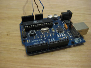
The wiring is very simple:
- Wire 5 to +5v on the Arduino
- G to GND on the Arduino
- S to Analog 0 on the Arduino
- Plug your Arduino into the computer.
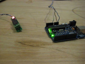
If you haven't wired up your thermocouple yet, the Alarm LED will light up, telling you that there is no thermocouple connected!
Connect Thermocouple
<div class="thumb tright"></div>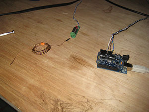
Wire up your thermocouple to the board. Thermocouples have polarity, so you need to insert it the right way to get a proper reading. If you insert it wrong, it will simply report the reverse of the real temperature.
Please note: the v1.0 board has a silkscreen error, and the +/- signs on the board are reversed. Sorry!!!
For thermocouple color codes, see wikipedia, or just experiment with the tester code below.
Upload firmware to Arduino
Create a new sketch and copy/paste the code below into it. Upload it to your Arduino.
void setup() { Serial.begin(9600); Serial.println("Start"); } void loop() { int raw = analogRead(0); int celsius = ( 5.0 * raw * 100.0) / 1024.0; Serial.print("Celsius: "); Serial.println(celsius); int fahrenheit = (((celsius * 9) / 5) + 32); Serial.print("Fahrenheit: "); Serial.println(fahrenheit); delay(1000); }
Try it out
<div class="thumb tright"></div>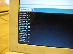
Start up your Arduino, and open the serial monitor. The exerciser code reads the thermocouple every second and outputs the current temperature in Celsius and Fahrenheit.
Make sure it reports the proper temperature at room temp. Use your fingers and watch the heat rise nearly instantly (if it goes down, reverse the thermocouple connection)
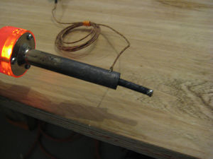
Finally, use something hot to give it a run for its money. If you still have your soldering iron hot, use the barrel as a heat source.

It should give you a high temperature reading. If so, congratulations, you have an awesome temperature sensor now!
++ Index