Gen7 Board 1.3.1
This page describes something which is no longer the most recent version. For the replacement version see: Gen7 Board-AVR 1.5
|
English • العربية • български • català • čeština • Deutsch • Ελληνικά • español • فارسی • français • hrvatski • magyar • italiano • română • 日本語 • 한국어 • lietuvių • Nederlands • norsk • polski • português • русский • Türkçe • українська • 中文(中国大陆) • 中文(台灣) • עברית • azərbaycanca • |
This supersedes Gen7 Board 1.3.
Release status: working

| Description | Generation 7 Electronics
|
| License | |
| Author | |
| Contributors | |
| Based-on | [[]]
|
| Categories | |
| CAD Models | |
| External Link | (none)
|
Contents
Upgrading from v1.3.1 to v1.4
To upgrade from a Gen7 v1.3.1 to a Gen7 v1.4 you can keep a lot of parts:
- The ATmega.
- Connectors and crimp pins, except the ones for the stepper motors.
- Heatsinks.
- Endstops.
- USB-TTL adapter.
- Stepper drivers (Pololus/StepSticks).
New parts needed for upgrading
This list shows all parts needed for assembling a Gen7 v1.4. If you're willing to unsolder items from your v1.3.1, this becomes less, of course.
Having all these parts and your older Gen7, you can start assembling it as if you had everything new.
| Name | Count | Designations | Vendors | Remarks | |||||
|---|---|---|---|---|---|---|---|---|---|
| Printed Circuit Board (PCB) | 1 | See Gen7 Board 1.4#How to get it | |||||||
| 0.6 mm Wire | 50 cm | Völkner | Digi-Key | Mouser | for the wire bridges on single sided PCBs | ||||
| Resistor 10 Ohms | 2 | R11, R12 | Reichelt | RS | |||||
| Resistor 560 Ohms | 2 | R14, R22 | Reichelt | Völkner | Farnell | RS | Digi-Key | Mouser | |
| Resistor 1 kOhms | 6 | R2, R6, R8, R10, R16, R18 | Reichelt | Völkner | Farnell | RS | Digi-Key | Mouser | |
| Resistor 4.7 kOhms | 2 | RT1, RT2 | Reichelt | Völkner | Farnell | RS | Digi-Key | Mouser | |
| Resistor 10 kOhms | 1 | R30 | Reichelt | Völkner | Farnell | RS | Digi-Key | Mouser | |
| Diode 1N4004 | 2 | D1, D2 | Reichelt | Völkner | Farnell | Digi-Key | Mouser | ||
| Coil 100 uH | 1 | L1 | Reichelt | Völkner | Farnell | Digi-Key | Mouser | ||
| Crystal 16 MHz or 20 MHz | 1 | U6 | Reichelt | Völkner | Farnell | Digi-Key | Mouser | ||
| Reset Switch | 1 | RESET | Reichelt | Völkner | Farnell | Digi-Key | Mouser | ||
| Ceramic Capacitor 0.1 uF | 12 | C5, C8, C9, C10, C11, C12, C13, C14, C16, C17, C18, C19 | Reichelt | Völkner | Farnell | RS | Digi-Key | Mouser | |
| LED 3 mm Green | 3 | LED2, LED5, +5V | Reichelt | Völkner | Farnell | Digi-Key | Mouser | ||
| LED 3 mm Yellow | 1 | Standby | Reichelt | Völkner | Farnell | Digi-key | Mouser | ||
| Ceramic Capacitor 22 pF | 2 | C3, C4 | Reichelt | Völkner | Farnell | RS | Digi-Key | Mouser | |
| Electrolytic Capacitor 10 uF | 2 | CT1, CT2 | Reichelt | Völkner | Farnell | Digi-key | Mouser | ||
| Electrolytic Capacitor 100 uF | 4 | C1, C2, C6, C7 | Reichelt | Völkner | Farnell | Digi-Key | Mouser | ||
| Jumper Header 2 Pin Pairs | 4 pair | J2/J3, J5/J6, J8/J9, J11/J12 | Reichelt | RS | Digi-Key | Mouser | cut them into appropriate pieces | ||
| Jumper Header 2 Pin | 2 | J13, J14 | Reichelt | Völkner | RS | Digi-Key | Mouser | cut them into appropriate pieces | |
| ICSP Header | 1 | CONN6 | Reichelt | RS | Digi-Key | Mouser | alternatively, assemble this out of the remainings of the Jumper 2 Pin Headers | ||
| Pololu Header | 8 or 4 | U2, U3, U4, U5 | Reichelt | Völkner | Digi-Key | Mouser | cut them to appropriate length, you want 8x 8 pins | ||
| Socket for the ATmega | 1 | U1 | Reichelt | Völkner | Farnell | Digi-Key | Mouser | ||
| MOSFET IRFZ 44N | 2 | Q1, Q2 | Reichelt | Völkner | Farnell | RS | Digi-Key | Mouser | |
| Molex KK100 2 Pin Header | 2 | TEMP1, TEMP2 | Reichelt | RS | DigiKey | Mouser | |||
| Molex KK100 3 Pin Header | 3 | X_MIN, Y_MIN, Z_MIN | Reichelt | RS | DigiKey | Mouser | Reichelt are tested to be fully compatible with Molex | ||
| Molex KK100 4 Pin Header | 4 | X_MOT, Y_MOT, Z_MOT, E_MOT | Reichelt | RS | |||||
| Cable Connector for the above | 4 | Reichelt | RS | ||||||
| Crimp Contact for the above | 16 | Reichelt | RS | DigiKey | Mouser | ||||
| Molex KK100 6 Pin Header | 1 | SERIAL | RS | DigiKey | Mouser | alternatively, use the same as for Jumper 2 Pin | |||
| Heater Header Molex 26-48-1045 (2 Pin) | 2 | HEATER1, HEATER2 | RS | DigiKey | Mouser | ||||
| Alternative to Heater Header: 2 Pin Screw Terminal | 2 | HEATER_1, HEATER2 | Reichelt | DigiKey | Mouser | ||||
| Disk Power Header | 2 | CONN2, CONN3 | Reichelt | RS | DigiKey | Mouser | also see DIY 4 pin molex connector | ||
| ATX24 Power Connector | 1 | CONN1 | RS | DigiKey | Mouser | Molex Mini-Fit 44206-0007. Also known as VAL-U-LOK (20 or 24 Pins). | |||
How to get it
PCBs
Get Gen7 Board PCBs from Traumflug.
As Gen7 is designed to be manufactured on a RepRap, you can make PCBs yourself, of course. How to do this on a RepRap or a general milling machine is described on the Gen7 main page. You want one "Gen7Board" PCB and up to six "Endstop" PCBs.
Yet another way is to purchase from one of the many houses specialized in manufacturing prototype PCBs. Gen7 is single sided, so this won't cost a fortune. If you want to sell excess copies, ask Traumflug for a commercial license.
Components
Get Gen7 Components Kits and Gen7 Connectors Kits from Traumflug.
If you want to assemble the collection yourself, see the #Parts Lists section.
Parts Lists
To assemble or verify these lists, open the layout with gEDA/PCB and export a "BOM". This will give you a list of all required components.
Special considerations:
- The Pololu Stepper Drivers want two single rows of 8 pin female connectors soldered into the board, so get these.
- The Pololu Stepper Drivers come with their male headers, so there's no need to purchase them separately.
- Don't forget enough (8-9) jumpers for the jumper headers.
- Resistors with 0.25 W are on the safe side, even if the footprint name reads "0.125".
- The Pololus can be operated with up to 35 V, so you may want like-rated electrolytic capacitors.
- You may want to add the cable side of the connectors, their crimp pins and some wire.
Electronic Components
This list is ordered to match the order of assembly.
| Name | Count | Designations | Vendors | Remarks | |||||
|---|---|---|---|---|---|---|---|---|---|
| 0.6 mm Wire | 50 cm | Völkner | Digi-Key | Mouser | for the wire bridges on single sided PCBs | ||||
| Resistor 560 Ohms | 2 | R14, R22 | Reichelt | Völkner | Farnell | RS | Digi-Key | Mouser | |
| Resistor 1 kOhms | 8 | R2, R6, R8, R10, R11, R12, R16, R18 | Reichelt | Völkner | Farnell | RS | Digi-Key | Mouser | |
| Resistor 4.7 kOhms | 2 | RT1, RT2 | Reichelt | Völkner | Farnell | RS | Digi-Key | Mouser | |
| Resistor 10 kOhms | 1 | R30 | Reichelt | Völkner | Farnell | RS | Digi-Key | Mouser | |
| Diode 1N4004 | 2 | D1, D2 | Reichelt | Völkner | Farnell | Digi-Key | Mouser | ||
| Coil 100 uH | 1 | L1 | Reichelt | Völkner | Farnell | Digi-Key | Mouser | ||
| Crystal 16 MHz or 20 MHz | 1 | U6 | Reichelt | Völkner | Farnell | Digi-Key | Mouser | ||
| Reset Switch | 1 | RESET | Reichelt | Völkner | Farnell | Digi-Key | Mouser | ||
| Ceramic Capacitor 0.1 uF | 12 | C5, C8, C9, C10, C11, C12, C13, C14, C16, C17, C18, C19 | Reichelt | Völkner | Farnell | RS | Digi-Key | Mouser | |
| LED 3 mm Green | 3 | LED2, LED5, +5V | Reichelt | Völkner | Farnell | Digi-Key | Mouser | ||
| LED 3 mm Yellow | 1 | Standby | Reichelt | Völkner | Farnell | Digi-key | Mouser | ||
| Ceramic Capacitor 22 pF | 2 | C3, C4 | Reichelt | Völkner | Farnell | RS | Digi-Key | Mouser | |
| Electrolytic Capacitor 10 uF | 2 | CT1, CT2 | Reichelt | Völkner | Farnell | Digi-key | Mouser | ||
| Electrolytic Capacitor 100 uF | 4 | C1, C2, C6, C7 | Reichelt | Völkner | Farnell | Digi-Key | Mouser | ||
| Jumper Header 2 Pin Pairs | 4 pair | J2/J3, J5/J6, J8/J9, J11/J12 | Reichelt | RS | Digi-Key | Mouser | cut them into appropriate pieces | ||
| Jumper Header 2 Pin | 3 | J13, J14, J15 | Reichelt | Völkner | RS | Digi-Key | Mouser | cut them into appropriate pieces | |
| Jumper for the two above | 9 | Reichelt | RS | Digi-Key | Mouser | ||||
| ICSP Header | 1 | CONN6 | Reichelt | RS | Digi-Key | Mouser | alternatively, assemble this out of the remainings of the Jumper 2 Pin Headers | ||
| Pololu Header | 8 or 4 | U2, U3, U4, U5 | Reichelt | Völkner | Digi-Key | Mouser | cut them to appropriate length, you want 8x 8 pins | ||
| Misc Header | 1 | MISC | Reichelt | Völkner | Digi-Key | Mouser | cut to appropriate length | ||
| Socket for the ATmega | 1 | U1 | Reichelt | Völkner | Farnell | Digi-Key | Mouser | ||
| ATmega 644 (or 644P) | 1 | Reichelt | Farnell | Digi-Key | Mouser | ||||
| MOSFET IRFZ 44N | 2 | Q1, Q2 | Reichelt | Völkner | Farnell | RS | Digi-Key | Mouser | |
All components on Mouser: $28.61 Updated: All components on Mouser $50
All components from Traumflug: €16.40 ($21.76) without VAT, €19.50 with VAT
Connectors
| Name | Count | Designations | Vendors | Remarks | |||||
|---|---|---|---|---|---|---|---|---|---|
| Motor Header Molex 26-48-1045 (4 Pin) | 4 | X_MOT_0.156, Y_MOT_0.156, Z_MOT_0.156, E_MOT_0.156 | RS | Digi-Key | Mouser | This is the one also used in Gen2 and Gen3 Electronics; | |||
| Cable Connector for the above | 4 | RS | DigiKey | Mouser | |||||
| Crimp Contact for the above | 16 | RS | DigiKey | Mouser | |||||
| Alternative to Motor Header: 4 Pin Screw Terminal | 4 | X_MOT_0.156, Y_MOT_0.156, Z_MOT_0.156, E_MOT_0.156 | Reichelt | DigiKey | Mouser | ||||
| Heater Header Molex 26-48-1045 (2 Pin) | 2 | HEATER1, HEATER2 | RS | DigiKey | Mouser | ||||
| Cable Connector for the above | 2 | RS | DigiKey | Mouser | |||||
| Crimp Contact for the above | 4 | RS | DigiKey | Mouser | same as the one for the motor headers | ||||
| Alternative to Heater Header: 2 Pin Screw Terminal | 2 | HEATER_1, HEATER2 | Reichelt | DigiKey | Mouser | ||||
| Disk Power Header | 2 | CONN2, CONN3 | Reichelt | RS | DigiKey | Mouser | also see DIY 4 pin molex connector | ||
| ATX24 Power Connector | 1 | CONN1 | RS | DigiKey | Mouser | Molex Mini-Fit 44206-0007. Also known as VAL-U-LOK (20 or 24 Pins). | |||
| Molex KK100 2 Pin Header | 2 | TEMP1, TEMP2 | Reichelt | RS | DigiKey | Mouser | |||
| Cable Connector for the above | 2 | Reichelt | RS | DigiKey | Mouser | ||||
| Crimp Contact for the above | 4 | Reichelt | RS | DigiKey | Mouser | ||||
| Molex KK100 3 Pin Header | 6 | X_MIN, X_MAX, Y_MIN, Y_MAX, Z_MIN, Z_MAX | Reichelt | RS | DigiKey | Mouser | Reichelt are tested to be fully compatible with Molex | ||
| Cable Connector for the above | 6 | Reichelt | RS | DigiKey | Mouser | ||||
| Crimp Contact for the above | 18 | Reichelt | RS | DigiKey | Mouser | same as for TEMP1, TEMP2 above | |||
| Molex KK100 6 Pin Header | 1 | SERIAL | RS | DigiKey | Mouser | alternatively, use the same as for Jumper 2 Pin | |||
| Optional: Cable Header for the above | 1 | RS | DigiKey | Mouser | only needed if you intend to solder your own USB-to-TTL cable | ||||
| Optional: Crimp Contact for the above | 6 | RS | DigiKey | Mouser | only needed if you intend to solder your own USB-to-TTL cable | ||||
| Heatsink for the MOSFETs | 1 or 2 | Reichelt | RS | DigiKey | Mouser | Please note that Reichelt ones are quite wide (18mm). Two of them won't fit. | |||
| Bolt M3 x 8 mm for mounting the MOSFET heatsink | 1 or 2 | ||||||||
| Washer M3 for mounting the MOSFET heatsink | 1 or 2 | ||||||||
| Nut M3 for mounting the MOSFET heatsink | 1 or 2 | Not needed for the Reichelt heatsinks, which come with an M3 tap already. | |||||||
| Heatsink for the Pololus | 4 | Reichelt | Völkner | RS | |||||
| Double Sided Heat Conductive Tape | 1 | Reichelt | Völkner | For glueing the Pololu's heatsinks, cut in appropriate pieces. Another working solution is a drop of Loctite glue. | |||||
All connectors on Mouser: $33.80
All connectors from Traumflug: €19.- ( = $25.10)
Miscellaneous
Generation 7 Electronics uses a TTL header for serial communications to the host. As many modern PCs lack a serial port, these need an appropriate USB to TTL cable:
| USB to TTL Cable | DigiKey | Mouser | Adafruit Industries | MAKE Store | MakerBot Industries | Watterott |
|---|
An alternative to the USB to TTL cable is the same electronics in form of a small breakout board:
| USB to TTL Breakout Board | Watterott | Sparkfun |
|---|---|---|
| Cable for the above | Watterott |
Another alternative is the E'go USB-TTL adapter, see instructions and limitations below.
Last not least, you need four stepper drivers, of course:
| Pololu stepper driver boards | Pololu stepper driver boards |
|---|---|
| Open Source Alternative | StepStick |
Assembly Instructions
- To find out which components to put where, have the layout on your PC screen available.
- PCBs fabricated with Voronoi paths need more heat, so raise your soldering iron's temperature by about 20 deg Celsius.
- Start with the flattest parts, usually wire bridges or resistors. This way, components won't fall out when you lay the PCB on it's front for soldering. Then continue with parts of raising height, connectors are usually among the last ones.
- The parts lists are sorted with that in mind, simply start at the top and assemble towards the bottom.
- To ease soldering jumper headers and similar components, put a small drop of cyanacrylate glue onto the component side before inserting them. As the PCB is single-sided, this won't hurt the solder point.
- The coil 100 uH looks just like a resistor. It's a bit thicker and comes with rings brown-black-brown.
- As 8 pin headers for the Pololus are expensive, many kits come with lower cost 10 pin headers. Cut 2 pins off of each.
- While soldering a pair of these headers, insert a Pololu to ensure good alignment.
Caution: Don't solder MOSFETs or insert the ATmega until after the Power Supply Checks.
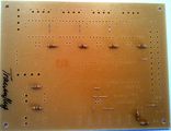
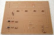
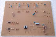
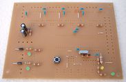
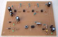
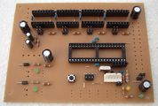
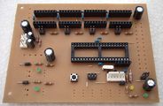
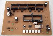
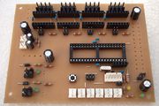
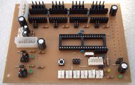
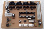
Assembly in Pictures
Click on the pictures to view them bigger.
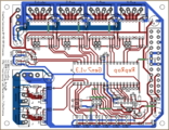
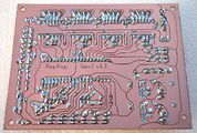
If you're unsure, always refer to this picture of the layout. The designators match those in the parts list.
For best solder quality, tin all solder points before inserting components.
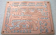
Start with the 9 wire bridges. They're the matte green tracks in the layout graphics.
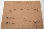
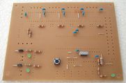
R14 and R22 have 560 Ω, so they're color-coded green-blue-brown.
The 6 resistors R2, R6, R8, R10, R16 and R18 have 1 kΩ, color code brown-black-red.
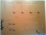
The 2 other resistors from R11 to R12 have 10 Ω, color code brown-black-black.
Near the thermistor connector there are two resistors RT1 and RT2 with 4.7 kΩ, or yellow-violet-red.
Last of the resistors is R30 with 10 kΩ, coded brown-black-orange.
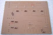
D1 and D2 are diodes, so you have to take care of polarity for the first time. Diodes have a white ring on the housing, which must end up closer to the boards boundary.
L1 looks like a thick resistor, but is actually a coil. Inserting direction doesn't matter here.
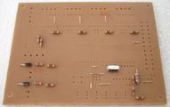
U6 is the crystal of ATmega's clock. Insert it in either direction, but try to heat each solder point no longer than 3 seconds.
The reset switch fits in two directions, both of which are fine.
Now it's a good time to insert all the 12 noise canceling capacitors. Again, direction doesn't matter.
LED2, LED5 and the +5V LED are green. As LEDs are diodes, direction matters. The longer of their legs is +, which happens to go into the upper hole for LED2 and LED5, and the left hole for +5V LED. You can also compare with the + sign in the layout.
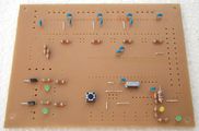
Same for the Standby LED, the longer leg goes into the upper hole.
C3 and C4 make the clock crystal swing, insertion direction doesn't matter.
CT1 and CT2 are electrolytic capacitors, which have a polarity. Their housing has a white stripe, which is minus (-) and goes into the lower hole.
C1, C2, C6 and C7 are electrolytic as well, the minus stripe goes to the outside or towards the bottom. Again, compare to the layout.
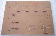
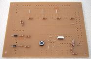
Now insert the headers for the Pololu's jumpers. Neither of the pins are electrically connected, so each direction is equal. As a mounting aid, you can glue them into the board with a tiny amount of cyanacrylate glue, applied to the plastics part only.
In the lower right corner, there are three jumper headers in single pairs.
The only jumper header with three pairs is for connecting the programmer.
Changing the appearance of the board quite a bit, insert all 8 female headers for the Pololus. Probably you have to cut them in length, e.g. with a pair of scissors. It's also a good idea to actually insert a Pololu while soldering, to assure a nice fit.
The Misc header currently isn't that important, insert it for completeness.
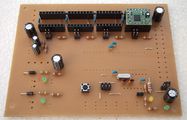
Last part from the components set is ATmega's socket. It snaps into place by it's self. It's also good tactics to solder the pins at the corners first, then every other pin and to finish with the remaining pins. This ensures good fit and moderate heat distribution.
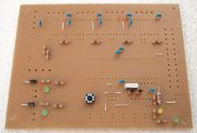
First of the connectors may be the serial one. The snap is on the side closer to the ATmega socket.
Two headers for connecting the thermistors.
Six headers for the endstops. Get the snap latches right, to be compatible with other boards.
Headers for the heaters and motors are bigger. Make sure to use sufficient solder, as these have to carry a bit of current.
The board is supplied with juice through disk power connectors. Again, don't save on solder.
Last connector is the ATX24. For now, you're done with soldering.
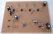
Wanna go in pretty soldering contest with me?


As you can see, neither the MOSFETs nor the ATmega are inserted yet. We'll come back to that later.
Setup
These steps show how to get from a soldered mainboard to a working one.
Possible Power Sources
Generation 7 Electronics has a plentitude of options to satisfy you machine's power needs.

Option 1
This is the recommended one. Take your PC power supply and plug in the ATX24, as well as both Disk Power connectors. This will supply the electronics with everything needed.
PC PSUs have two strings with several Disk Power connectors on each string. Each of the strings can supply about 10 Ampéres only, so make sure you plug in only one connector of each string into Gen7's headers.
In this scenario, the ATmega can run and talk to the host with the PSU turned "off" (in Standby mode). So, don't be surprised if you start working with your Mendel and the PSU is still quiet. Each G-code command requiring more juice will turn the PSU on, and some time after the last command off again.
Note: the ATX24 header is backwards compatible to the older ATX20 connector, so if you have a PSU with an ATX20 connector, plug in that. There's only one position where it fits (without pushing very hard) and there is no drawback in using an older supply:

Option 2
This is for people with a non-PC power supply. Make connectors feeding 5 V to the upper Disk Power header, as well as 12 V into both of them. The ATX24 is left empty.
No standby feature here, ATmega, Pololus, motors and heaters are supplied all the time.
Option 3
This allows talking to the ATmega only and may be useful for firmware programming. Leave the ATX24 and both Disk Power headers empty. The ATmega will be fed through the serial header. This assumes your serial header actually supplies 5V: some USB-TTL converters need soldering to enable this feature.
As said, this option won't allow the motors to move or heat the extruder.
Power Source Selection
After choosing an option for the power supply, you have to tell the board where to get 5V from.

In the lower right corner of the board you see three jumper headers.
- ATX24: recommended for option 1.
- Disk Power: recommended for option 2.
- Serial: required for option 3.
You may jumper one, and only one of them.
NOTE: Actually combinations "ATX24+Serial" and "Disk Power+Serial" are also possible and usefull if you need to supply power from Generation 7 board to the serial connector (for example, to power a max232 based converter board).
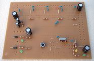
Power Supply Checks
With the 5 V selection jumper and all power connectors inserted, you can take a few measurements to make sure your brand new ATmega won't blow up when inserted.

- Red: power supply inserted according to any option. In case of an Option 1, PSU not yet activated.
- Blue: as above, with PSU activated or power supply according to Option 2. Not applicable to Option 3.
Note: in the picture, no 5 V selection jumper is inserted, but you need the right one here.
Checks:
- No smoke? Great.
- The yellow LED in the lower right corner is lighted? Even better.
- If you've chosen Option 1, short the two wire bridges like the dashed green line in the picture. This should activate the power supply.
- At the same time, the green LED in the lower right corner should go on as well.
- If you have a voltage meter, measure the voltages shown in the picture.
- Also, check each of the pins of the ATmega socket, none of them should have more than 5.5 volts.
- For extra security, check the pins in the lower row of the Pololus. Neither of them should exceed 5.5 volts as well.
With everything within the limits, you can pretty safely assume to not blow up the expensive parts when inserting them.
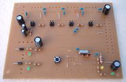
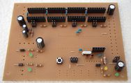
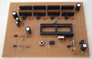
Insert Semiconductors
Now, with some safety tests done, it's a good time to insert semiconductors.

- Disconnect the power supply entirely.
- Solder the MOSFETs into place with the flat side towards the center of the board. Use sufficient solder, as high currents are flowing here.
- Mount the heatsinks. The picture shows the recommended placement.
- Insert the ATmega into it's socket. Like every integrated circuit, there's a notch (groove) on one end of the package. This notch faces towards the MOSFET side of the board, the un-notched end is close to the ATX24 header. Done right, you can read the text on the package from the ATX24 header side correctly.
Another, perhaps more sensitive heat handling solution is to put a big heatsink onto the MOSFET for the heated bed while leaving the other one free:

Prepare your Arduino IDE
Note: If you have an ATmega1284P CPU, you have to use Arduino IDE 1.0 or later (the avrdude supplied with the previous versions of this IDE don't know this chip yet.)
- Download and unpack or install the Arduino IDE.
- Also install Gen7 Arduino IDE Support.
- Fire up your Arduino IDE.
- Under Menu -> Tools -> Board, select your variant of Gen7 board (there should be four new entries). They differ in processor type and clock speed.
- Under Menu -> Tools -> Serial Port, select the correct serial/com port.
Bootloader
If you bought your ATmega with one of the Gen7 kits, the bootloader should have already been uploaded. Any other bootloader, like the one used for the Sanguino, RAMPS, Sanguinololu or whatever is also fine.
If you bought an factory fresh ATmega, e.g. from a general electronics supplier, the ATmega will be without bootloader. Bootloader binaries come with the Gen7 Arduino IDE Support package, so upload instructions can also be found there.
If you're in doubt, just continue with the setup. A missing bootloader will result in a timeout error when attempting to upload a firmware.
Serial Connection
It's recommended to either use a USB to TTL cable or USB to TTL breakout board. Custom solutions are possible, see #Customisations & Others.
Here's how you connect them, GND is always the pin to the left:


Simply plug the connector in, connect USB to your PC and a new serial port should show up in your PC's operating system.
Your First Firmware Upload
After all this assembling, and with this complex firmware thing ahead, whouldn't it be a good idea to upload some test firmware to test wether basic things work? Of course!
You can find such a test firmware in Gen7's Github repository.
- Download that file SetupText.ino. If it opens in the browser window, do a "Save as...".
- Prepare your Gen7 by inserting power plugs, the serial converter, the USB plug of that converter and so on.
- Start your Arduino IDE.
- With the IDE, open SetupTest.ino. You'll be asked if you want to create a folder of the same name, click "Yes".
- Make sure the right serial port and the right type of board is still selected in the Test menu.
- Hit the "Upload" button (the second from the right).
After a second or two, you should see something like
Binary sketch size: 2142 bytes (of a 63488 byte maximum)
in the black text field, and after another second of blinking on the serial connector, it should say "Done uploading." right above that text field.

Now you can safely assume uploading a firmware works. The test firmware has a few more features:
- If you open the IDE's serial monitor and listen at 9600 baud, you can read what the ATmega is doing. If you can read clear text, the serial line is working.
- Three or four seconds after the upload, the power supply should spring to life, blink the LED of HEATER1 a few times and turn the PSU off again.
- The same happens after each hit of the Reset button on the board, independently from the IDE or the serial connection.
Microstepping
Last not least, you probably want to set up microstepping to something other than the default. The default is halfstepping. Smaller microsteps make the motors run smoother, but also raise the computing load for the ATmega. The smallest steps possible are 1/16 microstepping.
Feel free to select different settings for each of the motors, e.g. 1/8 microstepping for threaded rod axes (Z) and 1/16 microstepping for belt driven axes (X, Y).
Selecting microstepping is done with the jumpers in front of each of the Pololus, they refer to MS2 and MS3. Allegro documents also know about MS1, which is hard wired to High in Gen7. Plugging a jumper sets High, while leaving the header free sets Low. Here's a detail picture of a Gen7, with MS2 set to High, MS3 set to Low:

The following table shows what you get with each combination:
| MS2 | MS3 | Microstep Resolution |
|---|---|---|
| Open | Open | Half step |
| Open | Plugged | Not allowed! |
| Plugged | Open | Eighth step |
| Plugged | Plugged | Sixteenth step |
You can change microstepping at any time, even while a motor is running.
Firmware
In principle, you can run any of the RepRap Firmwares on this board. Adjust the I/O pin layout, adjust compile time options for no secondary board/no RS485 and proceed. Just like Gen2, RAMPS or similar electronics.
Teacup Firmware
Teacup's Simple Installation instructions show nicely how to do this. Some tweaks are required for Gen7:
- Have your Arduino IDE prepared for Gen7, as explained above.
- Download the Gen7 branch instead of the standard download.
- Use the config.gen7-v1.1-v1.3.h and ThermistorTable.double.h you find there.
With config.h left untouched, at least something should move. This is fine for first tests, but not sufficient to have everything right for your machine. Edit your config.h further to match your machine and your setup. Config.h has a lot of comments inside the file, helping on the details. For example, STEPS_PER_M_X should be set according to your choice of microstepping.
Note that to test the extruder heat sensor, the extruder heater must be turned on!
Reprap software is in constant flux, so try to use recent software both for host software and slicing, or you may run into compatibility problems. For example, the original reprap host software may not report the temperature correctly (if at all). Using Pronterface for host software solved this problem for one user. Using Slic3r rather than Skeinforge solved another problem where the Teacup firmware would be stuck forever 'waiting for target temp'.
Repetier Firmware
Tested on 644 @ 20Mhz. See this post for sample config and pins files. Should be integrated into the default firmware soon.
Here is the github download page, and documentation is on the github wiki
FiveD Firmware
FiveD has been run succssfully on Gen7. As the ATmega pin layout of v1.3 almost matches that of v1.2, firmwares running on v1.2 continue to work on v1.3. Snuggles has kindly contributed his sources:
File:FiveD 20100610 for Gen7 v1.2.zip
To upload the Firmware do the following:
- Have your Arduino IDE prepared for Gen7, as explained above.
- Open the FiveD_GCode_Interpreter.pde file inside the FiveD_GCode_Interpreter folder with the IDE.
- Press the upload button in the IDE's toolbar.
- If there are no errors, you're done.
This should get you started, but don't forget to adjust STEPS_PER_MM in configuration.h to match your mechanics.
Sprinter, Marlin
These two are limited to 16 MHz electronics. Instead of fixing the software to allow faster speeds, their makers try to convince people 16 MHz is better than 20 MHz. Similar to how Golf GTI drivers try to convince people their car is better than a Porsche.
Update 2012-03-12 from a Marlin developer: Marlin now supports arbitrary clock frequencies, so 20 MHz should work properly.
Experimented with Marlin, Sprinter too?:
- To avoid continuous brown out resets we need to replace 100µH L1 coil by a 10µH one as in Gen7 1.5.
- English Forum thread: http://forums.reprap.org/read.php?181,175191,175191
- German Forum thread: http://forums.reprap.org/read.php?247,170384,171365
- Alternatively, 100µH L1 coil can be replaced by a strap, with a 100µF cap added in parallel with C19.
- To avoid bad temp messages at startup, thermistors must be continuously powered as described at the bottom of this page: Thermistors on 5 V Standby.
Other Configurations
The following should help to configure other firmwares.
Pinout

| Function | ATMega Name | Teacup | Original firmware | Direction in firmware |
|---|---|---|---|---|
| X Step | PC3 | DIO19 | 19 | Digital Output |
| X Direction | PC2 | DIO18 | 18 | Digital Output |
| X Min | PB7 | DIO7 | 7 | Digital Output |
| X Max | PB6 | DIO6 | 6 | Digital Output |
| Y Step | PC7 | DIO23 | 23 | Digital Output |
| Y Direction | PC6 | DIO22 | 22 | Digital Output |
| Y Min | PB5 | DIO5 | 5 | Digital Output |
| Y Max | PB2 | DIO2 | 2 | Digital Output |
| Z Step | PA5 | DIO26 | 26 | Digital Output |
| Z Direction | PA6 | DIO25 | 25 | Digital Output |
| Z Min | PB1 | DIO1 | 1 | Digital Output |
| Z Max | PB0 | DIO0 | 0 | Digital Output |
| Extruder Step | PA3 | DIO28 | 28 | Digital Output |
| Extruder Direction | PA4 | DIO27 | 27 | Digital Output |
| Power Enable | PD7 | DIO15 | 15 | Open Drain Output, active low |
| Motors Enable | PA7 | DIO24 | 24 | Digital Output |
| Heater 1 | PB4 | DIO4 | 4 | Digital Output |
| Heater 2 | PB3 | DIO3 | 3 | Digital Output |
| Temp 1 | PA1 | AIO1 | 1 | Analog Input |
| Temp 2 | PA2 | AIO2 | 2 | Analog Input |
Changes from v1.2:
- Fan 1 (PA0 / DIO31 / 31) is gone.
Customisations & Others
This part describes possible modifications - for advanced users only.
Non-12 V Voltages
While it's very practical to use 12 V from the power supply, Gen7 is prepared for other voltages, too. Even better, you can supply different voltages for motors and heaters.
Possible usages:
- 12 V for the heaters, 24 for the motors. This will still allow to use standard Reprap heating elements for the extruder and heated bed, while the motors can now run faster. Motor supply voltage is only limited by the Pololus and can go up to 35 volts.
- 12 V for the motors, 5 V for the heaters. This would load your power supply more evenly.
- 12 V for the motors, 3.3 V for something like EDM or inductive heated nozzles. Remember, the IRFZ44N can switch pretty fast, and the ATmega has frequency/PWM generators on board.
- ...
On where to supply what, see the picture above. Simply rewire the disk power connectors to your needs and make sure all power sources contact at least one GND pin, to give them a common ground.
The 5 volts on the upper disk power connector is not needed if you use the ATX20/24 connector, but don't supply a different voltage at this connector, or a voltage from a different power supply, either.
Serial Connection
If you want a custom solution, you can create one, of course. Just connecting an RS-232 port to the serial connector won't work, however, even if you ignored the different voltage levels. ATmega's serial signal is inverted (Logical 0 = 5V, Logical 1 = 0V). Here's the serial connector's pinout:

| 1 | 2 | 3 | 4 | 5 | 6 |
|---|---|---|---|---|---|
| GND | CTS (set to GND) | +5 Volts | RxD | TxD | Reset |
RxD is ATmega's pin 14 (data to the chip); TxD is ATmega's pin 15 (data from the chip).
With pin 3 you can feed the ATmega, if you have no other current source. If you have another current source, e.g. your power supply, you might have slightly different potentials of 5V though, so you better keep this pin unconnected.
Pin 6 is usually connected to the serial line's DTR. This triggers a reset each time you start a connection to the ATmega and is very convenient when uploading firmware - no pressing of the reset button needed, then. Arduinos have this hardwired. If you keep pin 6 free, press the reset button each time your IDE (avrdude) attempts an upload.
Using an E'go USB-TTL adapter
This converter is cheap, uses the Silicon Labs CP2102 chip and basically works:

| Gen7 | GND (Pin 1) | +5 Volts (Pin 3) | RxD (Pin 4) | TxD (Pin 5) |
| USB-TTL adapter | GND (Pin 5) | +5 Volts (Pin 6) | TxD (Pin 3) | RxD (Pin 4) |
Important here is to not connect both Reset pins.
Note 1: CP2102-based converters normally do not support auto-reset. Because of this, the Arduino IDE behaves like it's stuck when uploading the sketch, flooding the console with lines 'avrdude: Recv'. To work around this, press the reset button just a second before the uploading starts, which happens shortly after 'Binary sketch size is...' message appears.
Note 2: It is possible to add auto reset functionality to any adapter using this chipset by connecting the DTR "pin" of the chip itself directly to the RST pin on the adapter. Also note that the chip is a fairly difficult to solder QFN package.
Note 3: You need to select "AVR ISP" as the Programmer in the Arduino IDE, not "AVRISP mkII"
Suppliers of this adapter
- eBay.
Thermistors on 5 V Standby
Sometimes it's convenient to have the thermistor inputs on 5 V Standby instead of the regular 5 V supply. This enables reading temperatures while the power supply is turned off. This is a standard feature of Gen7 v1.4 and consumes only about 0.25 milliWatts at room temperature.
Nophead explained how to do it in the forum, Terramir came up with pictures: Thermistor always on. The black lines in Terramir's pictures show where to cut the copper tracks, the green lines show where to re-connect them. Thanks to both!