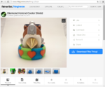
Diamond FolgerTech FT-5
Release status: Development

| Description | Diamond FolgerTech FT-5
|
| License | |
| Author | |
| Contributors | |
| Based-on | |
| Categories | RepRap Color 3D printing
|
| CAD Models | |
| External Link |
Diamond Hotend upgrade guide for FolgerTech FT-5
This is the official build guide intended for those who wish to modify FolgerTech FT-5 for the Diamond Hotend.
A little warning: this procedure will most likely void warranty on your device, so before proceeding please read this guide thoroughly and be sure you know and understand what you are about to do.

Contents
Part list
These are the parts needed for upgrading with the Diamond Hotend. For printed parts see the Thingiverse link at the bottom of this page.
Electronics
- 1 x RAMPS
- 1 x Stepper Expander
- 6 x Stepsticks
- 6 x 4-pin female header
- 8 x Adhesive PCB spacer (RS: 220-787)
- 1 x 2x5P IDC to 2x5P IDC cable from Ramps AUX-2 to Easy Expander, about 10 cm for further information on connections see the page Adding more extruders
- 2 x Power wire for Easy Expander
- Cable ties
- Adhesive pads
- 120 cm braided sleeve
- 1 x Display unit (Optional)
3D printed mount kit
Diamond Hotend
- 1 x Diamond Nozzle 1.7 mm version
- 3 x E3D Lite6 heatsink with bowden fitting
- 1 x Thermistor NTC 100k fitted with wire, about 70 cm or more
- 1 x Heater cartridge (12 Volt / 40 Watt)
- 1 x Axial fan (12 volt / 50x50 mm)
- 1 x Radial fan (12 volt)
Extruders
- 3 x MK9 extruder (motor, drivegear, injection molded parts, etc.)
- 3 x Optional: MK9 extruder motor wiring (may come as separate cables unless factory mounted to the motors)
- 3 x 4-pin pinheader for soldering onto motor wiring unless already fitted
- 12 x Heatshrink, about 1 cm for 4-pin pinheaders
- 3 x Bowden tube OD:4mm, ID:2mm, Length:650mm
- 3 x Model "JPC4-01" bowden tube push fitting for 4mm tube, 3/8" (9.5mm) thread diameter
Extruder mounts
- 3 x MK9 extruder mount
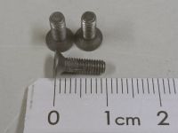
- 6 x M3x20mm
- Adhesive pads
Extruder cable mount
- 1 x Braided sleeve 30 cm
- 3 x Cable tie
- 1 x Cable tie mounting pad
Assembling
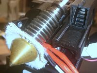
Cooling Shield
These instructions are written with bq Prusa i3 Hephestos in mind but adapt very well to the FolgerTech FT-5
If you haven't already done so, or you want the one with the blower fan option, download and print the Diamond Hotend Cooler Shield (http://www.thingiverse.com/thing:720520) or the Diamond cooler shield PRUSA i3 with blower addon (http://www.thingiverse.com/thing:1370444). For normal use we recommend printing the cooler shield in PLA. For printing with materials that require higher printing temperatures, we recommend printing the shield in ABS or another material with a higher glass transition temperature (Tg).
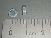
Insert the two M3 nuts into the hexagonal holes at the rear of the printed Cooler Shield and press them into place. If necessary use a soldering iron to heat the nuts and melt them into place.
The two holes are spaced 30.5 mm apart, hence it should fit most Prusa i3 printers, but check with your printer anyways - you may have to customize this part if your printer have different specifications.
If you are assembling the version with the blower pendant, insert a M3 nut through the designated internal slot.
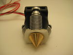
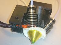
Apply a small amount of the thermal compound to the center hole of the Diamond Hotend.
Insert the heater cartridge into the center hole of the Diamond Hotend and press it in as much as possible. Wipe off excess compound. If there's no excess remove the heater cartridge and repeat from step 3 adding more compound. The heater cartridge must be inserted so far in that it will be held in place and partly covered by the lower fins of the HeatSinks. Failure in executing this step can lead to skewed Heatsinks, improperly tightened HeatSinks and even a leaking hotend, so please be sure to do this step right.
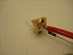
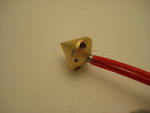
Dip the thermistor tip into the remaining thermal compound and press it into the 2 mm hole in the Diamond Hotend along with some millimeters of the PTFE tape tubings, which will keep the thermistor locked in place.
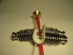
Stack the three Thermal Isolator Sheets, feed the wire ends through their corresponding holes, then firmly press the sheets onto the threaded part of the HeatSinks. Remove any insulator residue stuck in or on the threaded part.
Note:
At this point it is recommended to wind some PTFE Teflon tape (plumbers tape) around the threads of the three HeatSinks before assembling, this will help to avoid leakage. Another option is to use "liquid sealing" e.g. SISEAL which allows for better fitting between the hotend and HeatSink.
Observe orientation in relation to the thermistor and screw the HeatSinks loosely into the Diamond Hotend. Do not tighten yet, we will do this later.
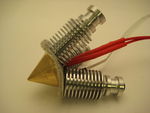
Grasp the wire ends from the heater cartridge along with the thermistor wire ends and feed them all the way through the pointy end of the Cooler Shield orienting the shield in such a way that the thermistor is located closest to the Cooler Shield mounting plate. Press the small black Bowden Fittings into the rear ends of the HeatSinks.
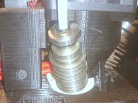
Making sure the wires remain in the central opening of the Cooler Shield, press the shield into the hotend assembly. The rear end of the HeatSinks must click equally into the grooves on the Cooler Shield. Retighten the HeatSinks but be careful not to over-tighten or the Heat Breaks might collapse.
Use 3 cable ties to attach the HeatSinks onto the Cooler Shield and the fourth cable tie to attach the wires onto the rear part of the Cooler Shield (the side which has a groove where the cables will fit).
Cut off any excess of the cable ties.
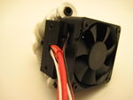
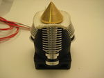
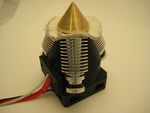
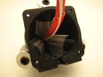
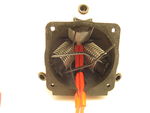
Mount the fan using 4 pcs M3 x 20 mm countersunk screws. Make sure to orient the fan such that the airflow goes down into the Cooler Shield (label side of fan pointing into the assembly) and the wires coming out at the same side as the other wires.
Hardware
- Dismount the original extruder
- Release the belts by loosening the bolts (Keep an eye out for the loose belt idler pulley on the left side)
- Dismount the x-carriage (Don't use a twisting motion if you plan on using the carriage later on, or it might break)
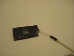
- Cut the fan wires by the ends, strip the last millimeters of insulation and solder longer wires onto the ends, remember to slide a piece of heat shrink over each wire before you begin soldering and carefully shrink the tubing around the solder joint using a lighter flame.
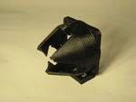
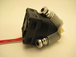
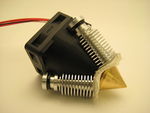
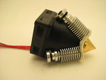
- Assemble the Diamond Cooling shield and mount the M3 and M4 nuts into the respective slots (for more detailed description on this procedure please follow the guide on Diamond Hotend).
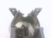
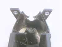
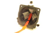
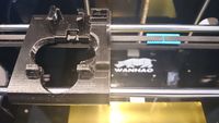
- Your cooling shield should now look something like this.
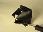
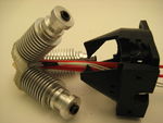
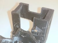
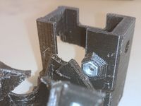
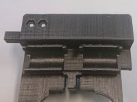
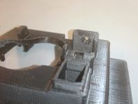
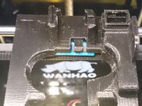
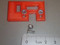
- Grab the x-carriage part and mount the two M3 nuts into the slots as shown on the pictures below. If they are too loose you may glue them into place and if they are too tight to fit you may heat them into place using a soldering iron like described on the Diamond Hotend page step two.
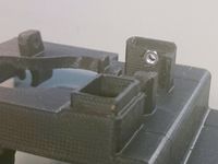
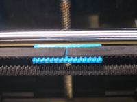
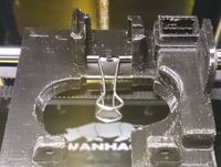
- Align each end of the belt onto the S2M beltclamp and glue these parts together using cyanoacrylate glue. Then align the linear bearings with the x-carriage and press it onto the bearings. After aligning the S2M beltclamp with the x-carriage (see picture) put a bulldog clip around the parts so that it holds the belt in place. Lastly pinch to remove each of the clip handles.
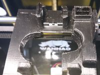
- Mount the top part onto the x-carriage using three M3x10 countersunk bolts. Please observe that the thermal insulations does not get stuck anywhere between the two printed parts.
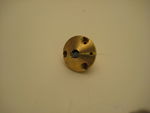
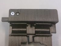
- Unscrew the Z-endstop switch and reinstall it onto the adapter using two M3 nuts and two M3x8 countersunk bolts. Make sure that the endstop switch is touched by the bed when it is at top position (in case it doesn't you can use the spacers from the original endstop mounting). *Replicator 2. No need for endstop spacer, just slide the endstop 2-3mm down.
- Assemble the bowden extruders (following the steps on Diamond Hotend).
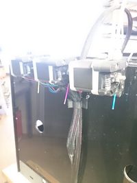
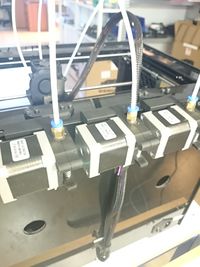
- Mount the extruders on the top rear edge of the printer.
- See "Attaching the bowden tubes" as well as Bowden tube hints section on the Diamond Hotend page.
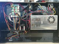
Electronics
These instructions will guide you briefly around removing the Mighty Board and install a RAMPS plus a Stepper Expander X1
Beware: Make sure that your RAMPS board and the Arduino MEGA can take the 24 volt from the original power supply of the Duplicator without releasing the magical blue smoke.- First turn the printer on its side and remove the lid of the electronics compartment.
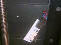
- Unplug all plugs from the Mighty Board and note where each of them goes
- Unmount the Mighty Board by unscrewing it from the frame of the printer.
- In order to align the USB socket of the RAMPS with the corresponding hole in the frame (6-8 mm) you may need to first glue a couple sheets of eg. acrylic in place. You may be using adhesive pads for this.
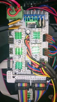
- Mount the RAMPS on top of the acrylic using adhesive PCB spacers.
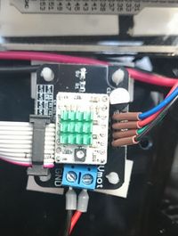
- Mount the Stepper Expander X1 (or pb ExtrudrBoard) again using the adhesive PCB spacers.
- Connect The Stepper Expander (or pb ExtrudrBoard) to the RAMPS AUX-2 using the 2x5P IDC cable.
- Move the power wires from the Mighty Board plug and connect them to the RAMPS
- Add the power wiring from terminals on the Stepper Expander (or pb ExtrudrBoard).
- Cut the motor plugs and solder on 4-pin female headers, remember to insert each wire through a piece of heat shrink prior to soldering, and carefully crimp it using a lighter flame.
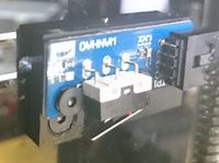
- While observing orientation insert five stepsticks in the vacant positions of the RAMPS board and the remaining stepstick into the Stepper Expander. (The trimpot on a standard A4988 driver should be closest to the power terminals on the Stepper Expander).
- Adjust the extruder stepsticks (or the motor drivers on ExtrudrBoard) to output 1.2 Ampere. See the link section for a separate guide on the subject of current limiting.
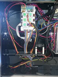
- Cut the 120 cm braided sleeve into 40 and 80 cm.
- Feed the extruder motor cables through the 40 cm braided sleeve.
- Also feed the Thermistor Heater and Fan wires through the 80 cm braided sleeve (80 cm).
- Secure the braided sleeves at the rear of the printer
- Tie all wirings in the electronics compartment so that no wires are blocking the airflow from the cooling fans to the stepper drivers.
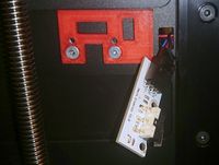
- Finally attach the optional display to the front.
Sources
Part files
- "Diamond mount for Replicator/Duplicator" on Thingiverse - http://www.thingiverse.com/thing:899168
- Z-endstop_holder.stl
- MK9_wide_right.stl
- S2M_beltclamp.stl
- Wanhao Diamond cooler shield ver3.stl
- Wanhao X-carriage ver3.stl
- Diamond Hotend Insulator - http://www.thingiverse.com/thing:720520/#files
- diamond_thermal_isolation.dxf
Links
- This guide - http://reprap.org/wiki/Duplicator_Diamond
- Diamond Hotend general guide - http://reprap.org/wiki/Diamond_Hotend
- Stepper Expander - http://reprap.org/wiki/Stepper_Expander
- Adding more extruders - http://reprap.org/wiki/Adding_more_extruders
- Current limiting your stepper drivers, see section "current limiting" - http://reprap.me/pololu.html


